Programmable logic controllers, or PLCs, are used to automate processes in industry. In the 1960s, the computerized processor replaced the relay logic control system. With the widespread use of PLCs in today’s automation industry, a technician is required to have a good understanding of their operation in order to perform maintenance and troubleshooting procedures.
Components
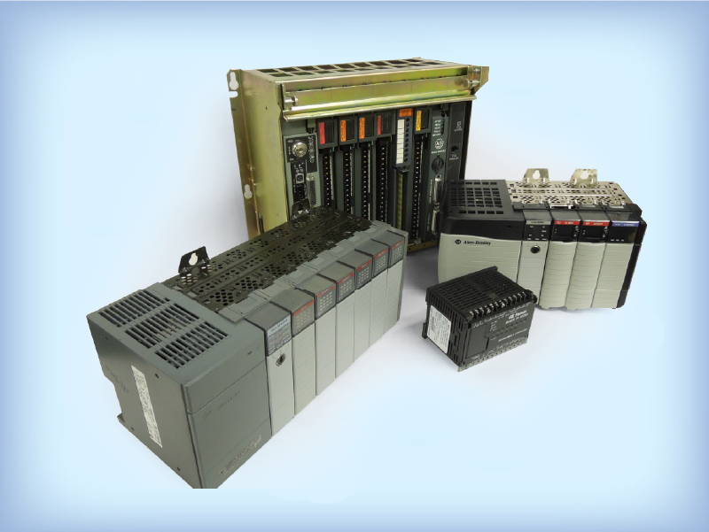
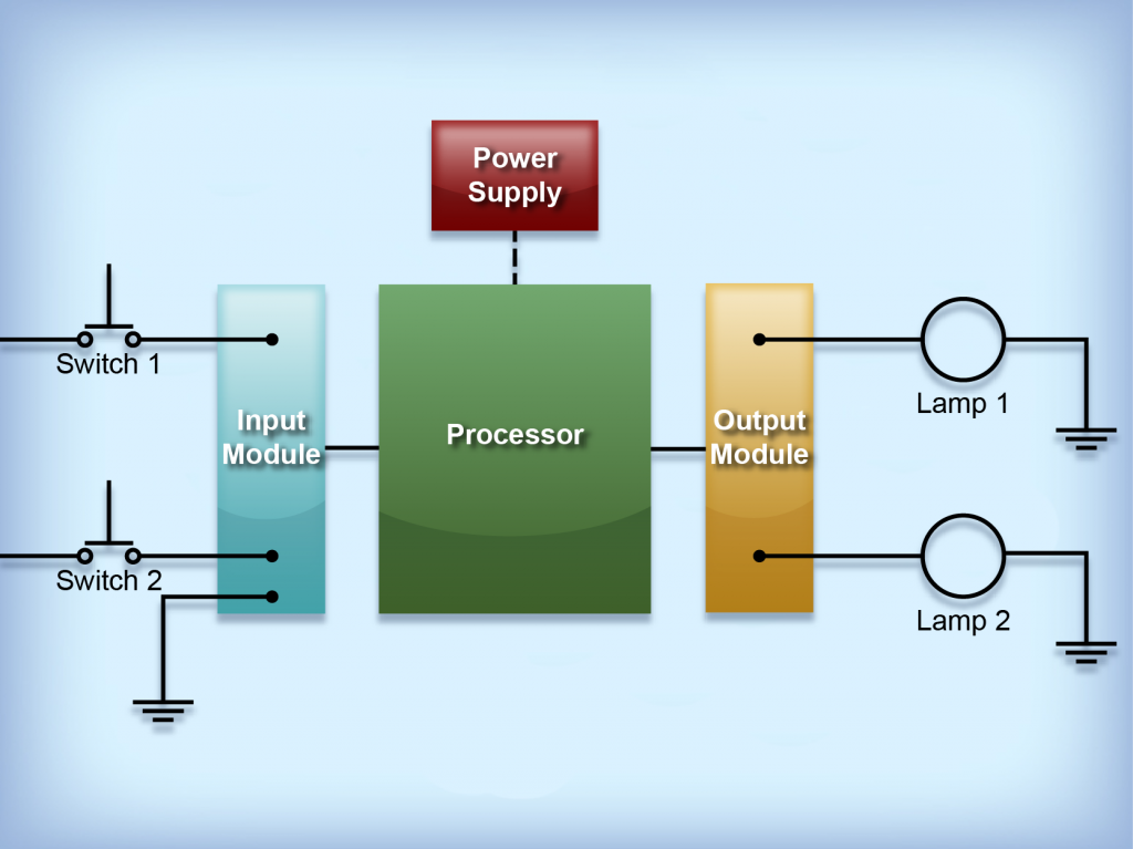
PLCs are comprised of a power supply and three basic components. Shown is an example of a typical PLC configuration. The power supply provides DC power to operate the PLC. It is supplied by a single-phase, 120- or 240-volt, AC line power. The processor stores and runs the PLC software programs. It also interfaces with the Input/Output, or I/O, modules as well as any external devices, and runs diagnostics. It essentially is the brains of the PLC. Input modules provide electrical connections between field devices, such as pushbuttons, limit switches, or photoeyes, and internal PLC operations in the processor. Finally, the output modules connect the PLC to external devices, such as lamps, relays, or solenoids. The output module controls power to external devices that start motors and other plant equipment.
Operation
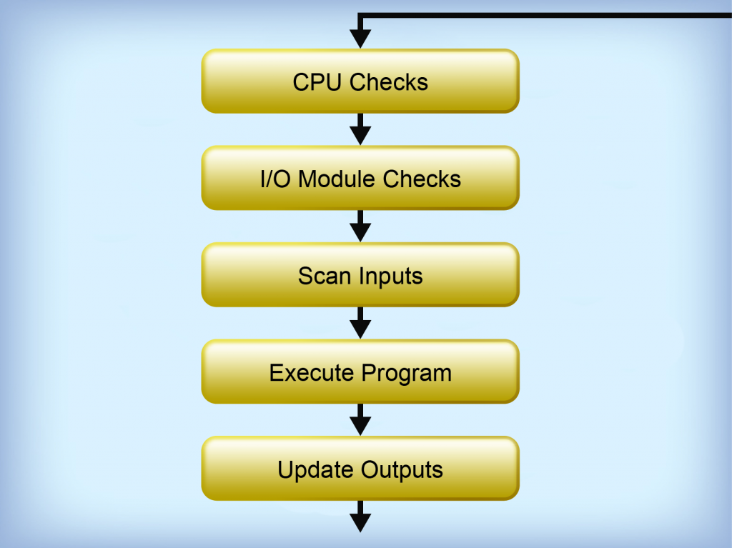
PLCs operate by continually scanning programs. When a PLC starts, it runs checks on the hardware and software for faults. If there are no problems, then the PLC will start the scan cycle. The scan cycle consists of three steps: input scan, execute program, and output scan.
Input Scan – The PLC looks at each input card to determine if it is “on” or “off” and saves this information in a data table for use in the next step. This makes the process faster and prevents input changes during the scan cycle from affecting the output.
Execute Program – The PLC executes a program, one instruction at a time, using only the memory copy of the inputs. For example, the program reads the first input as “on;” since the PLC knows which inputs are on and off from the previous step, it will be able to decide whether the first output also should be turned on.
Output Update – When the ladder scan is complete, the outputs are updated using the temporary values from the memory copy. Then, the PLC updates the status of the outputs based on which inputs were “on” during the first step, and the results of the executed program in the second step.
Ladder Logic
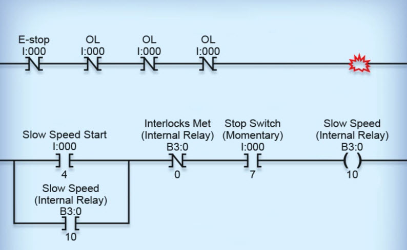
Ladder Logic is a programming language that is equivalent to that of a physical relay-based system. It uses graphical representations of relays and contacts to represent true and false statements.
Ladder Logic is broken up into rungs. A rung represents the conditions that have to be met in order to energize a coil. Ladders are read left to right, top to bottom. Note that Ladder Logic represents the program condition and not the actual electrical connections.
Advantages
The widespread implementation of PLCs has had many advantages in industrial applications, including system flexibility, ease of troubleshooting, space efficiency, low cost, testing, and visual operation.
Technology Transfer Services and our PLC experts provide custom and group PLC instruction to enhance your understanding and implementation of this invaluable technology. A visit to our expansive Programmable Logic Controller wiki page is a good first step to a deeper understanding of the subject.