Introduction
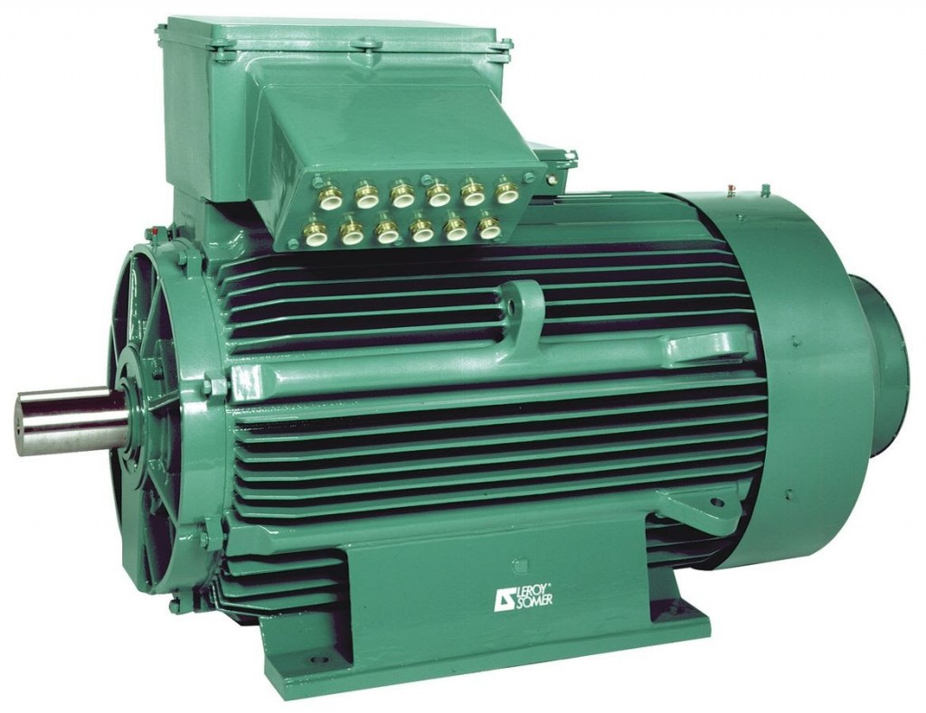
Electric motors are literally the driving force behind many industrial and residential processes. They provide rotational force to a large span of equipment from a large 500 HP motor spinning a centrifugal compressor to the small fan cooling your laptop. Motor failure can cause a complete production unit shutdown and millions of dollars in lost revenue. There are many methods for analyzing electric motor faults to predict failures. Some are simple and can be done with just a voltmeter, ammeter, or ohmmeter. Some are more complex and require special analytical instrumentation.
Voltmeter Testing
When checking a motor’s voltage, it is best to measure phase to phase. To do this, you should measure from phase A to phase B, A to C, and B to C. These values should be compared to the rated voltage, which is normally found on its nameplate. The maximum recommended deviation is 10%. If any of the three values recorded are greater than 5% off, you have an under- or over-voltage that can alter the operating condition of the motor.
Another thing to check for is voltage unbalance. Unbalanced voltages lead to unbalanced currents and, in turn, unbalanced magnetic fields, which can lead to adverse operating conditions for the motor. To find the voltage unbalance, you first need to find the average of the three phase-to-phase voltage readings as well as the percentage of the readings’ average. This percentage is multiplied by a certain factor based on the horsepower rating of the motor. The unbalance should not exceed 5%.
Ammeter Testing
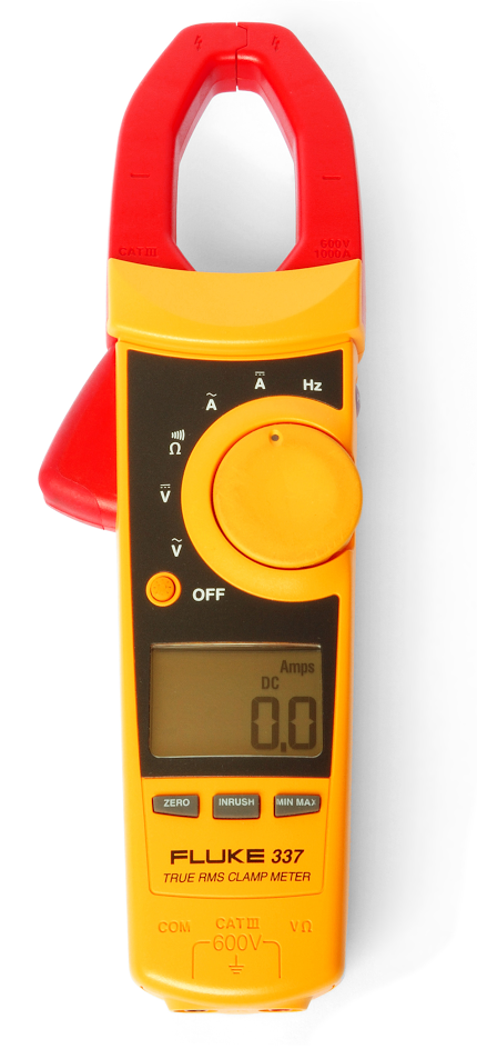
As with the voltages, the phase currents can be measured and give you an indication of an issue with the motor. The easiest way to measure the phase current is to use a clamp-on ammeter around each of the incoming phases. Once you have all three phase currents, you can find the average and then use the same method to find an unbalanced voltage to check for unbalanced current. The maximum recommended current unbalance is 7%.
Now that the average voltage and average current have been found, you can calculate the percentage of motor load. To do this, divide the average voltage by the rated voltage and divide the average current by the rated current. These two values are multiplied together then multiplied by 100%. If a power factor is supplied, you would then multiply all of this by the power factor. The result will give you the percent load the motor is being operated at. This value can be used to see if the motor is overloaded.
Ohmmeter Testing
There are different resistance checks you can perform on a motor. Two of the most basic are the windings and the insulation of the windings. To check the resistance of each winding, you need to measure from phase to phase just as was done with the voltage checks. A resistance unbalance (greater than 2%) between the phases could be indicative of a short, loose connections or broken conductors within the motor.
The other resistance is that of the winding insulation. A new motor ideally has an insulation resistance of greater than 1,000 megohms. As the insulation resistance goes down over the life of the motor, it becomes more susceptible to degradation. The insulation resistance should regularly be checked with a megohmmeter. A megohmmeter applies a DC voltage from the windings to ground, and the resulting current measured corresponds to the overall resistance of the insulation.

A megohmmeter can also be used to perform a Dielectric Absorption analysis, which is effectively a ratio between a 60-second and 30-second insulation resistance test. Also, you can test the Polarization Index, which is a ratio of a 10 minute to a 1minute insulation resistance test.
Motor Circuit Analysis
Motor diagnostics have evolved beyond what has been discussed so far. The tests up to this point have only been able to give an indication that there is a potential problem. By using low voltage sine wave outputs to excite the insulation system and surrounding magnetic steel dipoles, a complete diagnosis can be made by observing their reactive state.
One of the last measurements that can change due to a winding fault is inductance; therefore, a motor’s inductance can be used as a good comparative baseline. As windings get contaminated, overloaded, or shorts, the capacitive reactance of the windings change. If a lower voltage signal with low frequency is used, then the capacitive reactance will have a greater impact on impedance. This change in impedance, combined with the knowledge that the inductance hasn’t changed, gives us indications of what is wrong.
Surge Comparison Testing
Unlike the low voltage signal used by motor circuit analysis, surge comparison testing uses high voltage, fast rise signal. This is used to find turn insulation faults. When the voltage is high enough to cause an arc between two turns at a fault, the resulting signal can indicate the type and magnitude of the fault. The amount of voltage it takes depends on the distance across the fault point, how far it is into the coil, and the material across the fault point.
This test sounds as if it would be destructive to the coil’s insulation and, in the past, it was. There used to be reliance on the user’s interpretation of the signal but, currently, newer digital surge comparison testers monitor for when a partial discharge occurs before an arc forms and prevents the potentially destructive fault detection.
Summary
As you can see, there are multiple methods when it comes to electrical motor diagnostics, and this barely scratches the surface. Long gone are the days of simply checking the voltage, current, resistance, and making sure your bearings are greased. Today, with proper diagnostics, motor failure and the resulting loss due to downtime can be predicted and mitigated.