Today, robotics are used in a wide range of industrial applications that provide process solutions for material handling, material joining, paint dispensing and spot welding. FANUC Robotics is a leading manufacturing robot company in America. Their robotic systems are seen everywhere in industry including the food and beverage, consumer goods, automotive, air and space, plastics, wood, and pharmaceutical industries. In this article, we will be explaining the various types of components associated with a robot system.
Robots and the Controller
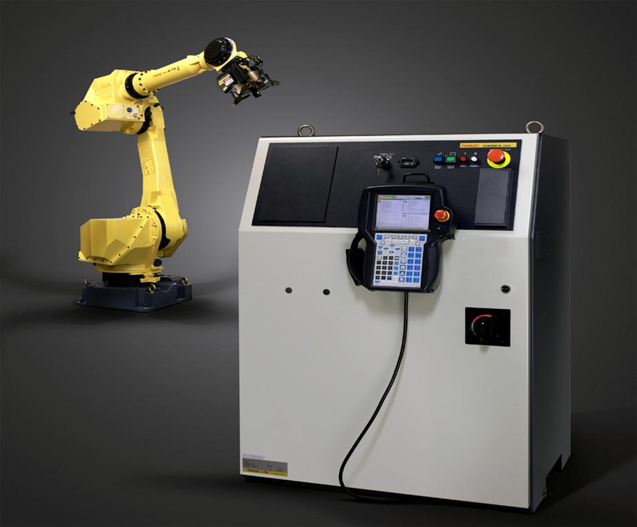
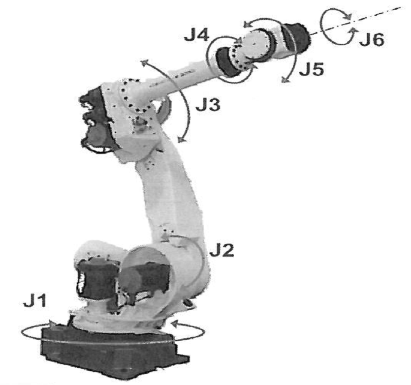
A robot is a series of mechanical links driven by servomotors. The area at each junction is called a joint, or axis. They typically have six points of axis. The first three axes are usually called the major axes (ex. J1, J2, and J3). The second three are called the minor axes (ex. J4, J5, and J6). The four components to a robot system are a mechanical unit, software, controller, and other peripheral equipment, which consists of any equipment not attached to the robot unit such as a wireless controller.
Mechanical Unit
Most units have six points of axis and each axis is driven by an AC servomotor. It uses a Serial Pulse Coder to determine its position. Most motors have an internal brake that is applied mechanically and released electrically by a signal from the servo amplifier.
Software
The software defines the function of the robot. It contains the communication protocols, fault isolation, and diagnostics. The motion of the robot is restricted mostly by software limits.
Controller
The controller converts program data into servo drive signals, allowing it to direct the operation and motion of the robot to a precise, desired location. It contains a power supply, operator controls, control circuitry, and memory. The controller’s memory stores application software, as well as user-defined programs and data. There are also communication ports and emergency stop connections.
Peripheral Equipment
Peripheral equipment is any item which is not a part of the mechanical unit, controller, or software. Examples would be proximity switches, limit switches, photo eyes, force sensing units, and Ethernet IP or other various communication interfaces. Some robots have the option of a wireless controller.
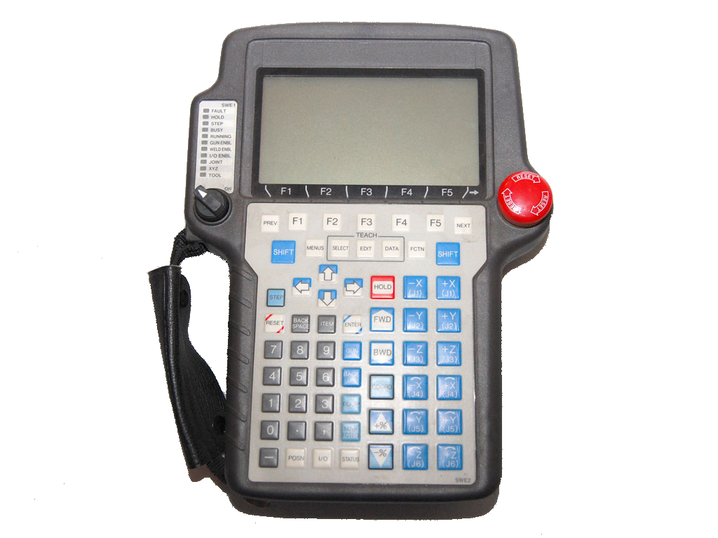
Above: Wireless Controller for a FANUC Robot
Motion System
The robot system uses the motion system to control robot motion. It is the motion system that regulates the characteristics of the robot’s movement including the path trajectory, acceleration and deceleration, termination, and speed. There are three different types of motion: linear, circular, and joint.
Linear
The robot will move in a straight line between two points.
Circular
The robot will move along the arc of a circle.
Joint
This type of movement is used when it is not important to define how the robot moves from position to position.
Operator Interface
The operator panel is part of the controller, which contains buttons, key switches, and connector ports for the user to input data into the robot. Here is an example of an operator interface.
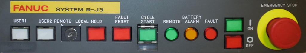
Battery Alarm
This alarm indicates that the backup battery voltage is low
Fault
This signal indicates that a fault condition has occurred
Remote
This signal indicates that the operator panel does not have motion control
Remote/Local
This switch allows the user to set the control to either remote (such as a PLC) or local (controller has control). In local mode, the controller cannot be made to start from an external signal (ex. PLC or Cell controller). While in local mode, the selected program within the Teach Pendant will automatically run when the user presses Cycle Start on the Standard Operator Panel.
On/Off
This signal indicates that the controller is either ON or OFF.
Cycle Start
This signal indicates that a program is running.
User LED #1, #2
The user can assign macros to run when these buttons are pushed. This item is user-definable.
Hold
This button pauses a running program without dropping the servo motors.
E-Stop
This button stops the robot immediately. An emergency stop condition can be created not only when the EMERGENCY STOP button is pressed, but also by a combination of operation selection, teach pendant ON/OFF switch, DEADMAN switch, and safety fence open and close.
Fault Reset
This button clears a fault message from the teach pendant screen after it has been corrected.
To learn more about Process Controls stop by our Industrial Wiki, then take the Free Module of the Month, Process Control Fundamentals, both available through the new ODESIE® site at www.myodesie.com. Also, be sure to check out http://www.fanucrobotics.com to learn more about FANUC Robotics.