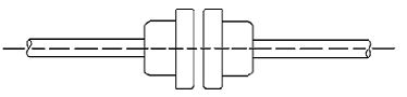
Accurate alignment is vital to the operating life of rotating equipment. Bearings, mechanical seals, packing, and couplings are all directly affected by the alignment of shaft center lines. The goal of the alignment process is to create a straight line through the coupling (as shown in the image below). The two coupled shafts are considered to be perfectly aligned when their center lines are coaxial at the operating condition.
It has been found that 50 to 70% of all vibration problems in machines are caused by misalignment. A thorough understanding of what conditions create misalignment will help us understand what needs to be done to correct it.
Types of Misalignment
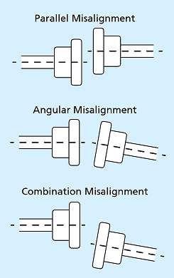
There are two basic types of misalignment: parallel (or offset) and angular. Both types can be found in the vertical and horizontal planes. Typically, a combination of offset and angular misalignment is found in both directions, as shown in the image below. To achieve our goal, we must correct both types of misalignment in each direction.
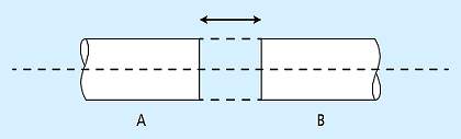
Two additional conditions must be addressed. The axial location of the machines and the baseplate are important to the operation. The proper shaft-to-shaft distance must be maintained, particularly when a limited end float coupling is being used (as shown in the image below).
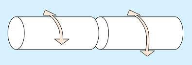
Torsional effect, or machine torque, may also need to be considered when aligning the equipment, shown in the image below. Machines may move horizontally during start-up and operation. These are not entirely alignment subjects, but we should be aware of their importance when performing alignments.
Causes of Misalignment
The basic causes of misalignment are:
- Movement of one piece of equipment relative to another due to thermal growth in one or both machines
- Piping strain or strain induced by electrical connections
- Torsional movement taking place at start-up or while operating
- Movement or settling of the foundation or baseplate
- Inaccurate or incomplete alignment procedures (human error)
- Misbored couplings
Any one of the above conditions will dramatically affect the alignment of equipment. If more than one of the conditions exists, the odds are highly against a machine running smoothly, quietly, or for any appreciable amount of time. Only after all of the situations have been examined and corrected can a craftsperson be assured of an accurate alignment job being achieved and maintained.
Effects of Misalignment
The effects of misalignment are all around us in a facility. High noise levels or constantly vibrating floors are strong indications of possible misalignment of machinery. Some of the other effects can be:
- Lost production
- Poor-quality products
- Higher than normal repair orders
- Increased spare parts purchases and inventory on hand
- Reduced profits
In addition to the financial impact on the company, the direct effect on the various machine components can be considerable. Bearings will run hot, causing them to fail prematurely. Mechanical seals, seal rings, and packing will leak. Loss of product and lubrication can occur. Couplings will fail due to excessive strain on the hubs. In severe cases, shafts can break, causing extensive damage to machines.
Indications of Misalignment
Misalignment in rotating machinery can be detected in many different ways. Some methods are incorporated into the plant’s preventative maintenance program. Others are inspections that could be used on a regular basis but usually are performed after the equipment has failed. Some of the indications of misalignment are:
- Wobbling shafts
- Excessive vibration
- Excessive bearing temperature
- Noise
- Bearing wear pattern
- Coupling wear
Wobbling of the shafts can be observed without any instruments or tools. It indicates that the shafts are improperly lined up and need adjustment. Misalignment is one of the leading causes of equipment vibration. In spite of “self-aligning” bearings and flexible couplings, it is difficult to align two shafts and their bearings so that no forces exist that will cause vibration. The significant characteristic of vibration due to misalignment is that it will be in both the radial and axial directions. If a bearing is found to have an abnormally high temperature and proper lubrication is present, then misalignment is probably the cause. Turbines, pumps, and other plant equipment have bearing temperature monitors or indicators. It is best to refer to the manufacturer’s literature for the correct bearing temperature parameters.
Some pumps and smaller equipment do not have any monitoring devices. For those, placing a hand on the bearing is a good indicator of excessive bearing temperatures. If the bearings on a particular pump are hotter than the bearings on similar pumps, misalignment could be the cause. Due to the possibility of the presence of high temperatures, care must be taken when touching bearings. Like vibration, noise can be detected simply by noticing a change in the equipment sounds during operation. All running equipment produces a certain normal amount of noise. Only if an operator is familiar with normal equipment noise will they be able to detect abnormal sounds. Possible misalignment may be detected through bearing and coupling inspections.
If bearings show signs of excessive wear, misalignment usually is the cause. The bearings will have to be replaced and the alignment corrected to prevent further bearing damage. The coupling parts should also be inspected. Any sign of excessive wear, especially if the wear is uneven, is a good indication of misalignment.
Alignment Tools
There is a multitude of methods available to perform accurate alignment, any of which can deliver the desired result. However, several precision tools are commonly used in alignment work. Dial indicators, parallel blocks, taper gauges, feeler gauges, a tape measure, a 6-inch rule, and a small mirror are all useful since each one has a part to play in doing alignments.
Dial Indicators
Dial indicators are probably the most widely used precision tools. They are available in various styles, sizes, and ranges. A back plunger type (as shown in the image below) is often used to take rim and face readings on couplings, to measure soft foot, and to monitor accurate machine moves. Their small size makes them easy and convenient to use.
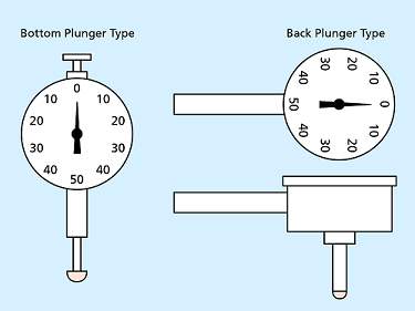
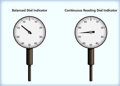
Bottom plunger-style indicators are used for taking runout readings on couplings and shafts, and for measuring misalignment. They come in two styles: balanced or continuous reading. Examples of both are shown in the image below. The dials are 1 inches in diameter or 2 1/8 inches in diameter. Their usable range is from 0.250 inch to as much as 12 inches. Typically, a 0.0250-inch or 0.500-inch travel indicator is used in alignment work.
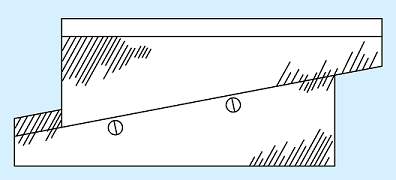
Parallels
Adjustable, or sliding, parallels, shown below, are used to measure gaps or holes. They usually are available in sets. Sliding parallels vary in length from 1 to 5 1/16 inches, are 9/32 inch thick, and can measure ranges from 3/8 inch to 1 to 2 inches. To check the size of a gap, the sliding parallel is inserted and expanded to the proper size. The parallel then is measured with an outside micrometer to determine the gap size. Sliding parallels can be used to take coupling hub face readings.
Thickness Gauges
The standard thickness gauge, also called a feeler gauge is a compact assembly of high-quality, heat-treated steel leaves of various thicknesses (as shown in the image below). The leaves usually vary in thickness by .001 inch, and the exact thickness of each leaf is marked on its surface.
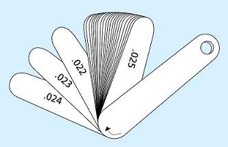
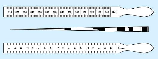
A thickness gauge is the measuring instrument commonly used to determine the precise dimension of small openings or gaps, such as those that must be measured in the course of aligning a coupling. To determine the dimension of an opening or gap, the steel leaves are inserted singly or in combination until a leaf or combination is found that fits snugly. The dimension is then ascertained by the figure marked on the leaf surface or, if several leaves are used, by totaling the surface figures. Another type of thickness gauge, not as widely known or used but ideally suited for coupling alignment, is the taper gauge (as shown in the image below). It is sometimes referred to as a gap gauge. Its principal advantage for coupling alignment is that it gives a direct reading and does not require trial-and-error “feeling” to determine a measurement. The tool end is inserted into an opening, or gap, and the opening size is read on the graduated face. Two measurement systems, inch and metric, are shown.
Micrometers
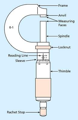
Another precision measuring instrument used for coupling alignment is the outside micrometer caliper, shown below. As its name implies, it is used to measure outside dimensions.
Outside micrometers are available as single units or as complete sets. A complete set of micrometers gives you the advantage of being able to quickly choose the micrometer appropriate for a specific situation. Two types of micrometer sets are generally available. One contains many micrometers of different sizes with a variety of frames. Such sets may contain anywhere from 3 to 24 micrometers and have ranges varying from 0 to 3 inches up to 0 to 24 inches. Different combinations of a ratchet stop or friction thimble and lock nut may be provided on micrometers in these sets. Micrometer sets of this type may be graduated in thousandths of an inch, ten-thousandths of an inch, or hundredths of a millimeter. The second type of outside micrometer set, contains an outside micrometer with interchangeable anvils and a set of standards. Micrometers of this type range from 0 to 4 inches up to 20 to 24 inches and are also available with Metric calibrations. An outside micrometer with interchangeable anvils is frequently used in the field to measure objects of varying sizes. The micrometer has an adjustable stop on the anvil to alter the overall anvil dimensions. Both types of micrometer sets are capable of measuring within the same size range and produce results with equal accuracy.
To learn more about Shaft Alignment, read our information on our Industrial Wiki and be sure to check out our Free module of the month, Types and Effects of Shaft Alignment, both available through the new odesie® site at www.myodesie.com.