The purpose of a voltage regulator is to maintain the output voltage of a generator at a desired value. As load on an AC generator changes, the voltage will also tend to change. The reasons for this change in voltage is the change in the voltage drop internally across the armature winding caused by a change in load current and the changes in power factor.
Because of changes in voltage, due to these factors, AC generators require some auxiliary means of regulating output voltage.
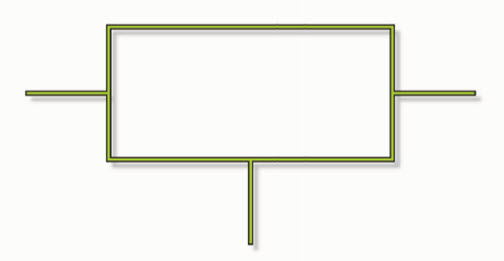
Shown here is the electrical symbol used for a voltage regulator. A voltage regulator is an electronic device connected to the output of a power supply to maintain the output voltage at its constant rated value. This is typically accomplished through the use of resistors.
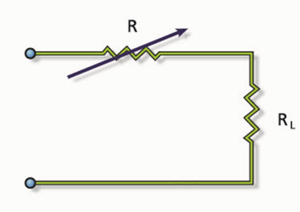
The second diagram shows a simple series voltage regulator. It includes a variable resistor, abbreviated as R, connected in series with a load resistor, or RL. The variable resistor can be adjusted so that the voltage output through the system can remain constant.
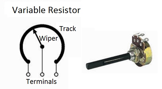
One method is the potentiometer. A variable resistor used as a potentiometer will have all three terminals connected. This arrangement is normally used to vary voltage. If the terminals at the ends of the track are connected across the power supply, then the wiper terminal will provide a voltage that can be varied from zero up to the maximum of the supply.
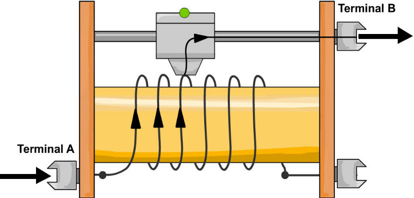
A rheostat is the simplest way to use a variable resistor. Rheostats can be commonly seen in light dimmers and audio control knobs. Two terminals are used: one connected to an end of the track, the other to the moveable wiper. Turning the spindle changes the resistance between the two terminals from zero up to the maximum resistance. Rheostats are often used to vary current; for example, rheostats can be used to control the speed of a motor or the rate at which a capacitor charges.
Diodes can also be used as voltage regulators.
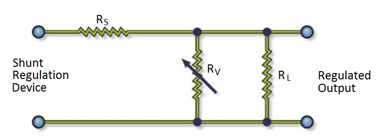
The diagram above is a simple shunt voltage regulator.
In the simple series voltage regulator, a voltage dividing action is used to obtain regulation. The amount of current through RS is now determined by the shunt regulating device RV, a variable resistor. The larger the current through RS, the higher its voltage drop and the lower the voltage across RL.
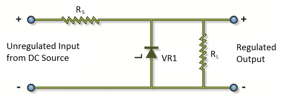
The breakdown diode, or Zener, is an excellent source of variable resistance. Zener diodes come in voltage ratings ranging from 2.4V to 200V, with tolerances of 5, 10, and 20 percent, and power dissipation ratings as high as 50 watts. The Zener diode will regulate to its rated voltage with changes in load current or input voltage. Referring to the Zener diode shunt-type voltage regulator shown here, the Zener diode VR1 is in series with fixed resistor RS.
For more information about voltage regulators and other industrial equipment and systems, follow us on social media or visit our website at www.techtransfer.com.