A PID controller combines the proportional response to a change while eliminating the offset error. It anticipates changes by measuring the initial rate of change for accurate control. Setting up a PID controller or tuning to a process loop is a little more involved than simpler controllers.
Proportional plus reset plus rate controllers combine proportional control actions with integral and derivative actions.
Proportional-Integral-Derivative
For processes that can operate with continuous cycling, the relatively inexpensive two position controller is adequate. For processes that cannot tolerate continuous cycling, a proportional controller is often employed. For processes that tolerate neither continuous cycling nor offset error, a proportional plus reset controller can be used. For processes that need improved stability and can tolerate an offset error, a proportional plus rate controller is employed.
However, there are some processes that cannot tolerate offset error, yet need good stability. The logical solution is to use a control mode that combines the advantages of proportional, reset, and rate action. This article describes the mode identified as proportional plus reset plus rate, commonly called Proportional Integral Derivative (PID).
Proportional Plus Reset Plus Rate Controller Actions
When an error is introduced to a PID controller, the controller’s response is a combination of the proportional, integral, and derivative actions, as shown in Figure 1.
Assume the error is due to a slowly increasing measured variable. As the error increases, the proportional action of the PID controller produces an output that is proportional to the error signal. The reset action of the controller produces an output whose rate of change is determined by the magnitude of the error. In this case, as the error continues to increase at a steady rate, the reset output continues to increase its rate of change. The rate action of the controller produces an output whose magnitude is determined by the rate of change. When combined, these actions produce an output as shown in Figure 1.
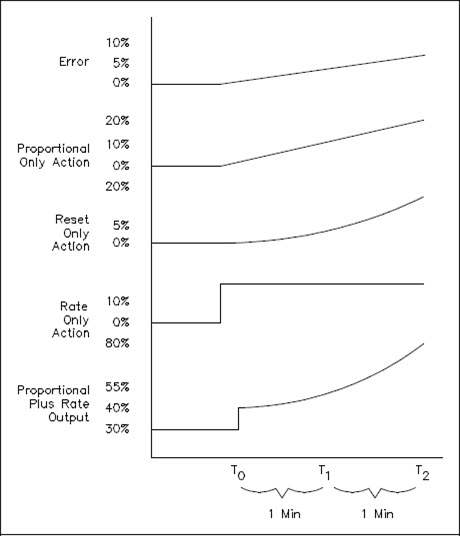
Figure 1 PID Control Action Responses
As you can see from the combined action curve, the output produced responds immediately to the error with a signal that is proportional to the magnitude of the error and that will continue to increase as long as the error remains increasing.
You must remember that these response curves are drawn assuming no corrective action is taken by the control system. In actuality, as soon as the output of the controller begins to reposition the final control element, the magnitude of the error should begin to decrease. Eventually, the controller will bring the error to zero and the controlled variable back to the setpoint.
Figure 2 demonstrates the combined controller response to a demand disturbance. The proportional action of the controller stabilizes the process. The reset action combined with the proportional action causes the measured variable to return to the setpoint. The rate action combined with the proportional action reduces the initial overshoot and cyclic period.
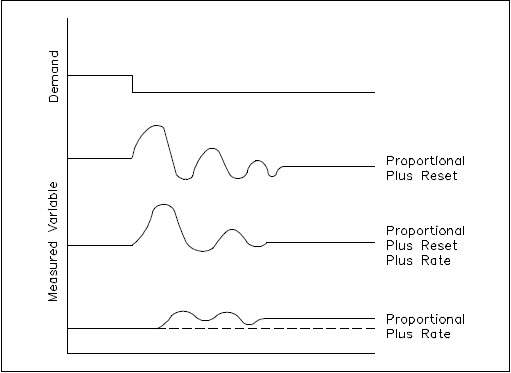
Figure 2 PID Controller Response Curves
For more information on Process Controls, sign up for our online training at www.myodesie.com or contact us at sales@techtransfer.com for a class at your facility.