Electrical maintenance requires a basic understanding of electrical theory and electrical safety.
Basic Electrical Theory
For a full understanding of electrical theory, please click here.
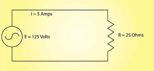
One of the most important theories in electricity is Ohm’s law. It basically defines how electricity will behave in electrical circuits. This is not to say that there are no other laws that define behaviors in more complex electrical circuits. For the time being, however, we will consider Ohm’s law only. The equation is:
”’E = I x R”’
Putting some values to this equation, if a circuit has a resistance of 25 ohms and a potential of 125 volts, the current that is drawn in this circuit would be 5 amps. Schematically, the circuit looks like the one shown in ”Figure 1.” This basic circuit will give you some understanding for the next subject that we will discuss: electric shock.
Effects of Electrical Shock
An important concern when working near electrical equipment is the effects of electrical shock on the human body. When we understand what these effects are, we can examine the other electrical hazards found on the job.
Most people are aware that the principal danger from electricity is that of electrocution, but few really understand just how minute a quantity of electric energy is required for electrocution. Actually, the current drawn by a 7-watt, 120-volt lamp passed from hand to hand or from hand to foot is enough to cause fatal electrocution. Just as it is current and not voltage that heats a wire, it is current that causes physiological damage.
Different values of 60-hertz alternating current (AC) and their effects on an average human are listed in Table 1. In short, any current of 15 mA or more may be fatal, those between 100 mA and 4 amperes are probably fatal due to heart failure, and those above 5 amperes may be fatal from severe burns. It is a fact, however, that shocks in this last current range are statistically less dangerous than those in the 100 mA to 4 amperes range. In view of the wide diversity of injuries derived from contact with electric energy, it is only logical that there must be minimum exposure to energized parts to prevent electric shock or electrocution.
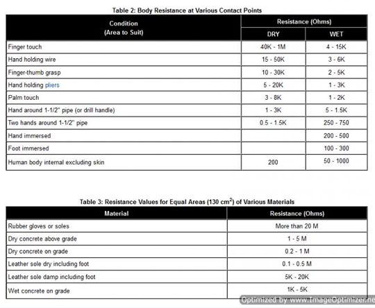
Ohm’s law may be used to determine the current, which is the value of interest, with the human body serving as the resistive element of the circuit. The E of Ohm’s law is the voltage of the system itself. The R, which is the variable, is actually the controlling factor. Essentially, it is the human skin, along with such factors as area of contact, tightness of contact, dryness of the skin, and the presence of any cuts, abrasions, or blisters that causes the resistance to vary. Except for the skin, human resistance is about 250 ohms per arm or leg, and 100 to 500 ohms from shoulder to shoulder or hip. The more muscular the person, the lower their body’s resistance will be. Skinny arms or legs and those made up principally of fat have higher resistance. Bone too has a high level of resistance. Table 2 shows the range of human resistance variations. The total human circuit resistance is, of course, the sum of the two contact resistances and the internal body resistance. Use Table 3 to compare human resistance to various materials.
Troubleshooting Procedure
When given a problem, for instance the lights being out, the fan not working, an outlet not working, or another electrical problem, there are a few simple steps to determine what is wrong, if anything, and what needs to be done to correct it. The first step is to never overlook the obvious. Is the switch off, the bulb blown, or the circuit breaker tripped? Many times, something simple will be the answer to the problem.
If the answer is not immediately apparent, then we begin the troubleshooting process. First, find the electrical prints for the circuit involved. Blueprints provide a road map in locating and isolating circuits, as well as identifying the location(s) of the various pieces of equipment associated with a circuit.
The next step is to determine if the piece of equipment is getting any power to it. If it is, then the equipment is defective and needs to be repaired or replaced.
If there is no power at the equipment, the source of the break in the circuit must be determined. Look for any physical damage to the conduit or connection boxes associated with the circuit. If those are OK, determine where the approximate middle of the circuit is and its closest connection box using the prints. At the box, check and see if any power is present at the box. If yes, go to the next connection box going toward the equipment. If no power is there, go to the next connection box going back toward the power supply. Continue doing this until the break can be isolated.
Once the break is found, the circuit must be de-energized to make the repairs. Repairs should never be made on live electrical circuits.
If it is a break at the splice, then you can re-splice, re-insulate, and restore the circuit. If it is a break between two connection boxes, a new section of cable must be pulled.
For a maintenance mechanic, troubleshooting is a method of finding the cause of a problem and correcting it. This is a very important job because the entire facility’s operation may depend on the troubleshooter’s ability to solve the problem. Some guidelines for good troubleshooting are:
- Use a clear and logical approach
- Work quickly
- Work efficiently
- Work economically
Determining Circuit Parameters
When we are making repairs or adding additional equipment to an existing circuit, there are several things that must be taken into consideration:
- What is the present loading on the circuit?
- What is the appropriate wire size for this circuit load, including the additional loading?
- Is the circuit protection adequate with the new addition?
Most of this information can be found in the National Electrical Code 2002 (NEC®).
Circuit Loading
The loading on the existing circuit can be determined by making measurements and looking at the installed design capabilities on the electrical prints. Measurements can be done using a clamp-on ammeter.
Determining Wire Size
According to NEC® Article 210.19, the rating of a branch circuit shall have an ampacity no less than the maximum load to be served. Where a branch circuit supplies continuous loads or any combination of continuous and non-continuous loads, the minimum branch circuit conductor size before the application of any adjustment or correction factors shall have an allowable ampacity no less than the non-continuous load plus 125% of the continuous load.
Determining Circuit Protection
In the NEC®, the sections and articles mentioned are not the only ones that may apply. The sections and articles reference other sections and articles that must be used for specific applications.
Replacing a 120-Volt Outlet
- Open and tag the power supply circuit for the outlet being replaced.
- Using the VOM as a voltmeter, check the voltmeter on a known live circuit to ensure that the meter is working properly.
- Using the voltmeter, check that the outlet to be replaced is de-energized.
- If the outlet shows that it is de-energized, check the voltmeter on a known live circuit to ensure that the meter is still working properly and did not fail when you checked the de-energized outlet.
- Remove the cover plate and outlet from the box.
- Replace with a new outlet, using care to restore the wires to their original positions.
- Replace the cover plate.
- Reenergize the circuit and test the outlet for proper voltage.
Installing Three-Way Switches
In the following description, there are two diagrams shown. Figure 2A) shows a three-way switch circuit where the supply goes to the switch first using a raceway; in Figure 2(B), the same circuit is shown using cable instead.
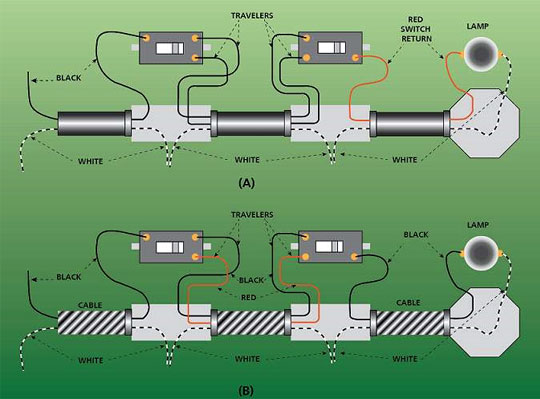
The three-way switch has a common terminal (darker) and two traveler terminals (brass). There are no “ON” or “OFF” positions on the switch. The color red is used as the switch return, but any color other than white, gray, or green could also be used. The travelers should be a different color than the switch return (e.g., a pair of blue wires, a pair of yellow wires, etc.)
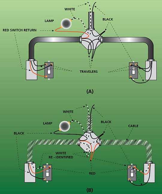
When using cable to wire three-way switches, the NEC 200.7(C)(2) permits the use of conductors with white, gray, or three continuous white stripes as the switch return only if the insulation is permanently identified by painting or another effective means at each location where the conductor is visible and accessible. Figure (A), below, shows a three-way circuit with the supply going to the light fixture first using a raceway; in (B), the same circuit is shown using cable.
Lighting Systems
The basic types of lights include:
- Incandescent
- Fluorescent
- High-intensity discharge (HID)
Incandescent Lighting
This type of light accounts for more than half of all the lamps sold in the US. These lamps come in a variety of voltages, wattages, sizes, shapes, and base types. Some of the older types of lamps are no longer manufactured due to legislation enacted in 1994 and have been replaced by more efficient types. As with all equipment that is to be replaced, lighting must be replaced with like models or a suitable substitute or a dangerous condition may result.
In an incandescent lamp, the filament (tungsten) is heated to a high temperature. The resulting glow produced when current is passed through this low-resistance wire is what produces a light. To aid in the longevity of the light, the air is removed and replaced with an inert gas such as argon.
These lamps have the lowest efficiency, as they normally are operated at lower temperatures to increase the longevity of the lamp.
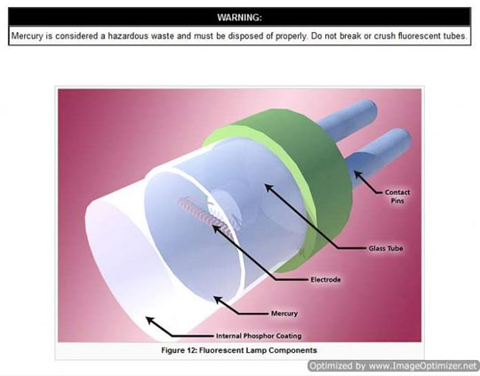
Fluorescent Lighting
The NEC considers fluorescent lighting to be electric discharge lighting®. The lamp (in the image below) is a glass tube with contacts at each end. There is a phosphor coating on the inside of the glass that enables the light to be seen. The glass tube contains an inert gas and a small amount of mercury.
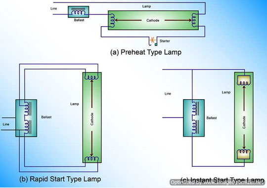
The fluorescent lamp normally requires a ballast to start the lamp. The older types, shown below(a), have a starter, which is a plug-in type can that allows the cathodes to heat up, allowing the lamp to fire. The newer lamps use rapid-start ballasts and do not require the use of a starter. There are two main types of ballasts: high output and very high output.
There are two types of starterless lamps: rapid start, shown below in (b), and instant start (c). The instant-start kind requires the use of single-pin lamps. The instant-start lamps do not require preheating the cathode, and the ballast has a higher output voltage than that of the rapid start.
A special ballast is used where the lamps are subjected to low temperatures (<50°C), such as might occur outdoors. These are marked with the minimum operating temperature. The ballast generates heat and, according to the National Fire Protection Association, is the second leading cause of electrical fires in the United States. Underwriters Laboratories (UL) has developed a standard for thermally protected ballasts, designated Class P. These ballasts have a sensor that detects the internal temperature of the ballast and opens the ballast circuit if the temperature reaches 194°F (90°C).
Due to the possibility of the thermal protection failing in the close position, which can result in overheating and fire, the circuit should be protected with inline fuses to isolate the defective ballast.
Compact fluorescent lamps are the newest type and have a life span of ten times that of an incandescent lamp with about three times the light output per watt. The base of the lamp fits directly into an incandescent lamp base.
Replacing Ballast in Fluorescent Lighting Fixture
Hanging fluorescent light fixtures are an inexpensive source of overhead light for garages, basements, etc., but they rely on a component called a ballast in order to function. When it goes bad, the light is useless. Replace the bad ballast, and the fixture will be good as new.
Safety Precautions
- Ensure power is de-energized.
Tools Required
- Screwdriver
- Wire stripper
- Wire cutter
- Wire nuts
- Fluorescent ballast
Procedure:
1. Determine the problem.
- If the bulbs in a fluorescent fixture are flickering, first make sure the ends of the bulbs are making a good connection.
- Try replacing one or more of the bulbs with a spare new bulb; sometimes one bad bulb will affect the performance of others in the same fixture.
- If the bulbs are good and they are still flickering, the problem is probably in the ballast.
2. Remove the old ballast.
- Before beginning work, be sure to unplug the fixture or turn the power off.
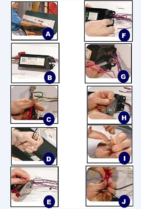
- Carefully remove the cover and bulbs(B). It is a good idea to wear safety goggles.
- Remove the inner cover to get to the ballast, which is a small black box. (C).
- Use a circuit tester on the black and white wires to make sure there is no current. (D).
- Disconnect/separate the wires coming from the ballast and the “feed line” wires (E).
- With wire cutters, cut the other two sets of wires going to the ballast (F).
- Loosen any nuts or screws holding the old ballast in place and remove the ballast.
- Take the old ballast with you to the electrical supply store to ensure purchase of the same size replacement.
3. Install the new ballast.
- The new ballast will have the same assortment of colored wires as the old.
- Be sure to place the new ballast in the proper direction (G).
- The colored wires will match up if it’s installed properly.
- Mount the new ballast onto the fixture using the same fasteners as before (H).
4. Connect the new wiring to the existing wiring.
- Reconnect the new wiring to the existing wires, matching color to color.
- If there are two sets of wires of a given color, it doesn’t matter how they are attached. Just be sure to connect blue to blue, red to red, etc.
- To connect the wires, strip a little of the colored insulation off each wire (I).
- Twist the bare ends of each pair of wires together and secure them with a wire nut (J).
- Repeat this process for all of the wires until complete.
- Check to make sure all of the wiring connections are snug.
5. Finish the project.
- Tuck the wires into the middle of the fixture.
- Replace the cover over the ballast, covering the wiring.
- Replace the bulbs and turn the power back on.
Note: Ensure that the wires are not pinched when restoring the cover.
High-Intensity Discharge Lamps
There are three types of lamps in this category: mercury, metal halide, and sodium. The light is produced in an arc tube inside a glass bulb. The lamp will continue to produce light if the outside bulb is broken.
Broken bulbs should be removed from service as soon as possible. With the outer bulb broken, harmful ultraviolet light is produced.
Mercury and metal halide light produce a strong blue-content light, while sodium lamps produce a light that is orange in color.
Alternating Current Motors
Alternating current (AC) motors can be divided into two major types: single-phase and polyphase motors. Single-phase motors normally are limited to fractional horsepower ratings up to 5 horsepower. They are commonly used to power such things as fans, small pumps, appliances, and other devices not requiring a great amount of power. Single-phase motors are not likely to be connected to complicated motor control circuitry and will not be discussed in this text.
Polyphase motors comprise the majority of motors needed to drive large machinery such as pumps, large fans, and compressors found in industrial facilities. These motors have several advantages over single-phase motors in that they do not require a separate winding or other device to start the motor, they have relatively high starting torque, and good speed regulation for most applications.
There are two classes of polyphase motors: ”induction” and ”synchronous.” The rotor of a synchronous motor revolves at synchronous speed, or the speed of the rotating magnetic field in the stator. The rotor of an induction motor rotates at a speed somewhat less than synchronous speed. The differences in rotor speed are due to differences in construction and operation.
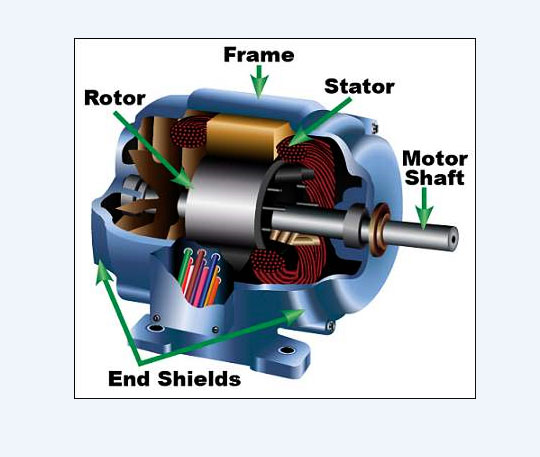
Induction Motors
Three phase squirrel cage induction motors (seen below) are perhaps the most commonly used motors in industrial applications. They are relatively small for their given horsepower and have good speed regulation under varying load conditions. They are simple in construction and rugged, so they cost little to manufacture. The induction motor has a rotor that is not connected to any external sources of power. It derives its name from the fact that the AC voltages are induced in the rotor due to the rotating magnetic field of the stator.
To learn more about Electrical Maintenance, read our information on our Industrial Wiki and be sure to check out our Free module of the month, Preventive Maintenance, both available through the new odesie® site at www.myodesie.com.