The terms software and firmware both refer to digitally stored programs and data structures that are read and written by computers. In the PLC world, software is usually reserved for computer applications that allow the logical creation, monitoring, and troubleshooting of a PLC program. One example of PLC software is the RSLogix program developed by Allen-Bradley for use with their controllers. Firmware can be referred to as the actual program a PLC uses to execute logical instruction. Firmware is often stored in internal memory or on Electrically Erasable Programmable Read-Only Memory (EEPROM). EEPROMs can be used to store program backups if there is a program fault or a sustained power loss to the PLC.
HMI Human Machine Interface
The basic purpose of an HMI is to allow convenient and intuitive graphical interface with a process and for control systems to be more interactive and user-friendly. HMIs provide a simple display that helps an operator determine machine conditions and make simple settings. The following are the most common uses of HMIs:
- Display of machine and process faults and status
- Simple operational commands such as stop/start
- Monitor of production/process counts and values
Ladder Logic Diagrams
The ladder logic used in PLCs today was once referred to as relay logic due to the implementation of physical relay coils used to control processes. Relay logic is now known as ladder logic because when the logic circuit schematic is laid out with electrical notation, it resembles a ladder with separate rungs, perpendicular between rails, and containing symbols used to represent Boolean logic expressions such as AND, OR, and NOT.
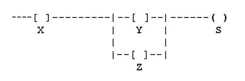
Figure 1: Ladder Logic
The example in Figure 1 shows two rungs containing a series of relays denoted as X, Y, and Z. These are inputs, while the symbol for S is an output.
The logical expression for this circuit is S=X AND (Y OR Z). If normally open contacts X and Y are closed, there is an output at S. Likewise, because of the OR function of Y and Z, there also is an output at S if X and Z are closed, but Y remains open. Any combination of Boolean expressions can be used in ladder logic, including but not limited to AND, OR, NOT, NAND, NOR, and XOR.
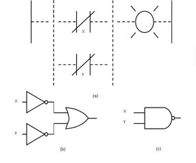
Figure 2: NAND Circuit
The two NOT gates leading into the OR gate in Figure 2(b) represent the normally closed contacts in Figure 2(a). The NOT gate function reverses the logic of any incoming signal, turning a HI into a LO and vice versa. When multiple rungs are connected to a single output on a ladder logic diagram, an OR function exists, as represented by the OR gate in Figure 2(b). The NAND gate functions just like an AND gate, creating a logic HIGH output in the presence of logic HI inputs X and Y. The only difference is the addition of the NOT function, reversing the output from a logic HI to a logic LO so that two HI inputs equal a LO output. Understanding the logic of this circuit, you can see that to turn the lamp off, X and Y must be HI. It is common when examining logic circuits to refer to logic levels as true or false, with true representing logic HI and false representing logic LO.
Logic Instructions
In order to use the PLC and make simple edits, it is necessary to understand some basic commands. The commands are all entered in ladder logic format, and many of them are based on nomenclature used in relay logic. There are timers, counters, coils, and contacts, among other commands.
For detailed information on PLCs, including their commands, visit our free Industrial Wiki or contact us at sales@techtransfer.com to set up a class at your facility.