
PLC Software
In a previous blog entry, we covered the basics of Programmable Logic Control, including components and operation. In this installment, we will discuss PLC software. Software is used in a PLC to create user projects and programs, which allow the PLC to operate. The software allows each user to create individual and unique programs for each type of PLC.
Software vs. Firmware
The terms software and firmware both refer to digitally stored programs and data structures that are read and written by computers. Although they may seem interchangeable, they have distinct definitions.
Firmware
Firmware can be referred to as the actual program or operating system a PLC uses to execute logical instructions. Firmware often is stored in the internal memory or on electrically erasable programmable read-only memory (EEPROM).
Software
Software is usually reserved for computer applications that allow for the logical creation, monitoring, and troubleshooting of a PLC program. Software is written to assist the installed firmware. One example of PLC software is the RSLogix™ series developed by Allen-Bradley for use with their controllers.

Human Machine Interface
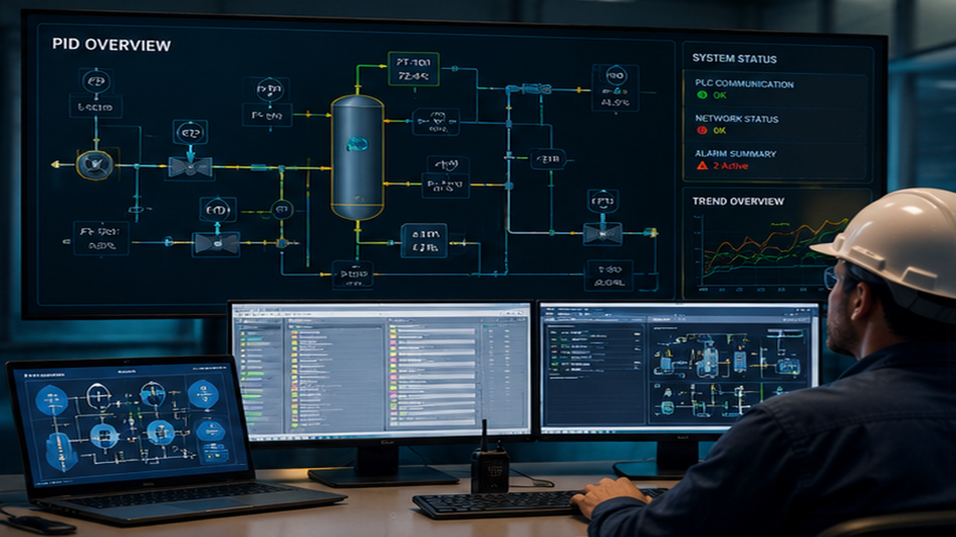
The basic purpose of a human-machine interface, or HMI, is both to allow convenient and intuitive graphical interface with a process and for control systems to be more interactive and user-friendly. An HMI provides a simple display that helps an operator determine machine conditions and alter simple settings.
Graphical user interfaces (GUIs) accept input via devices, such as a computer keyboard and mouse, and provide articulated graphical output on the computer monitor. Hardware is the equipment used to interface with the software or GUI of an HMI. Some examples are touch screens, keyboards, and mice.
Commands
In order to use the PLC and make simple edits, it is necessary to understand some basic commands. The commands are all entered in ladder logic format, and many of them are based on nomenclature used in relay logic, such as bit instructions, timers, counters, and various other commands.
Bit Instructions
PLCs use logical representations of relays and contacts called bit instructions. There are no physical contacts or relays inside a PLC. The following are examples of Allen-Bradley commands.
- Examine if Closed (XIC) – This command functions as the input or storage bit.
- Examine if Open (XIO) – This command is similar to the XIC, except it works in reverse.
- Output Energized (OTE) – The OTE instruction is used to control a bit in memory.
- Output Latched (OTL) – The OTL instruction functions much the same as the OTE, with the exception that once a bit is set with an OTL, it is latched on.
- Output Unlatched (OTU) – The OTU instruction is a retentive output instruction that only turns off a bit (it cannot turn on a bit).

Timers
A timer is simply a control block that takes an input and changes the output based on time. Some common instructions include:
- Timer On Delay (TON)
- Timer Off Delay (TOF)
- Retentive Timer On (RTO)

Counter
A counter simply counts the number of events that occur on an input. There are two basic types of counters: up counters and down counters.
Other Commands
There are many other instructions in ladder logic. The following instructions are a just few examples.
- Reset Command (RES) – The RES instruction is an output instruction that resets a timer or counter.
- Move (MOV) – The MOV command is an output instruction that copies a value from a source address to a destination.
- Math Commands – PLCs have a wide variety of available mathematical commands. These commands simply perform the indicated math function on any valid instruction address data or any number.
To learn more about PLCs in an easy to use and efficient way, check out our Free Module of the Month, Process Control Fundamentals, available through the new odesie® site at www.myodesie.com.