
The use of prints is the most efficient way to convey information about systems and equipment that cannot be expressed by words alone. By using symbols and notes, a large amount of information that might require many pages of written description can be presented in a condensed form on one diagram. Understanding the basics of print drawings and the information that they convey will allow personnel to more efficiently disseminate information required to carry out a task or implement system modifications.
Borders
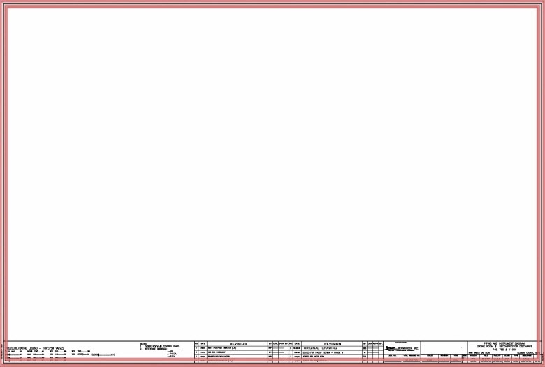
Technical drawings will include a border. The border frames the drawing area within a sheet to provide a uniform look to a set of drawings and is a requirement for any technical drawing in accordance with ISO 5457, or ISO 80.
Legend
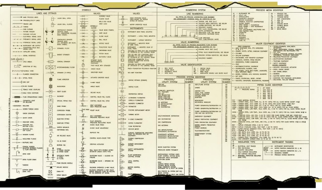
Prints often contain a legend. The purpose of a legend is to give the individual using the drawing a guide to the symbols, abbreviations, and indications used in each specific set. The legend for a set of drawings should only be used with that set due to variances among different legends. Legends often are located on a separate sheet in front of a set of drawings or on the corner of the drawing itself.
Bill of Materials
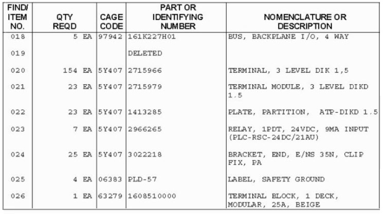
A bill of materials (or BOM) is a list of all the materials and their quantities used in the manufacture or assembly of a machine or structure. This listing can be part of an assembly drawing or contained in a separate document. Bills of materials are used primarily for assembly or installation drawings. The BOM is sometimes called a Parts List, Materials List, or Schedule of Parts.
A bill of materials usually details the following information:
- Vender/Supplier Code, also called the Cage Code
- Item Number – a sequential list of each part on the table
- Part Number – the manufacturer’s universal number for that part
- Description – the noun name of the part
- Quantity – the number of parts required for one assembly
Title Block
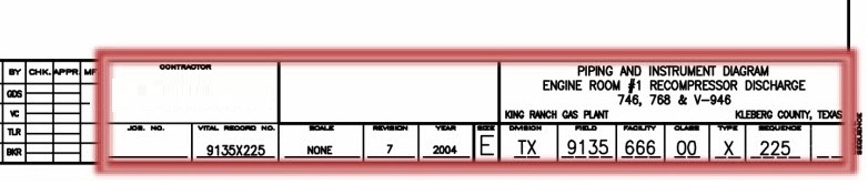
The title block on a drawing serves two purposes: it provides the reader with information about the object depicted on the drawing and it aids in print identification and filing. The title block is usually located in the lower right-hand corner of the blueprint so that when the print is correctly folded, the title block may be seen for easy reference and for filing and storage.
Typical areas of a title block include:
- Drawing number
- Drawing title
- Sheet number for multi-page drawings
- Drawing scale
- Signature block for at least the drafter and approver
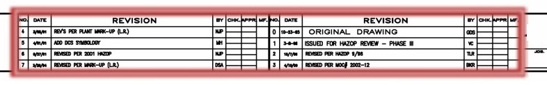
Revision Block
When revisions are made to a technical document, relevant information regarding the change will be listed within the revision block. The revision block will include revision number, date, and author.
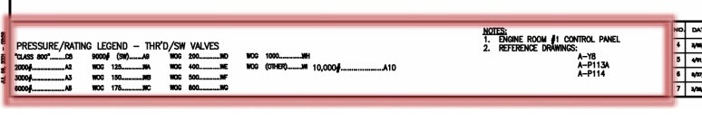
Notes
General and drawing specific notes, as well as any pertinent references, will be displayed within the notes area of a drawing. Notes can include anything from generic general work instructions to equipment specific installation information, and everything in between.
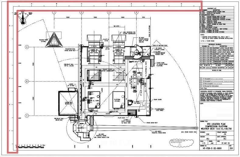
Zone Identifier
Zone identifiers help to communicate item locations within a drawing more effectively and quickly to other personnel. Distinct vertical and horizontal units located along a drawing’s border offer a method to assign a communicable value to a specific location within a drawing.
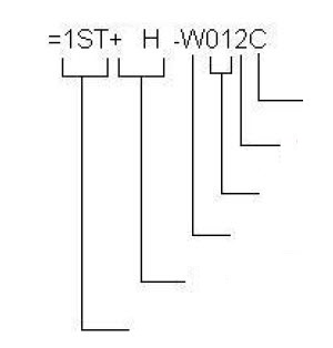
Numbering System
Some drawing numbering systems provide more information about a particular drawing than just a serialized number. For these numbering systems, each part number grouping represents a separate data category. Example categories could be location, equipment type, or revision. Using a smart numbering system gives the technician information using just the drawing number.