This article discusses the fundamentals of welding, including welding safety, energy sources, electrode types, weld joint description, symbols, and properties of weld joints. Next, the types of welding processes are described, including shielded metal arc welding, gas tungsten arc welding, gas metal arc welding, and oxyacetylene welding. In the final portion, we review other methods including oxyacetylene torch cutting, oxyfuel cutting, air arc cutting with carbon, brazing, and soldering.
Fundamentals of Welding
This section provides background information on the fundamentals of welding and includes a discussion of the following pertinent topics:
- Welding safety
- Energy sources
- Electrode types
- Weld joint description
- Weld joint symbols
- Weld joint properties
Welding Safety
The dangers in welding come in three major categories: eye injuries, burns, and inhalation of fumes and gases. Any one of these can seriously injure a worker, and all three must be guarded against while on the job. Safety can never be taken for granted.
Arc Welding Safety
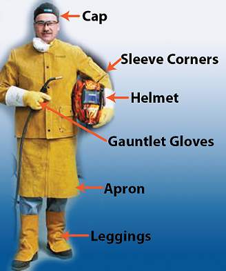
Welding gloves and a welding helmet are necessary for all arc welding tasks. Additional items of personal protective apparel are recommended as conditions and hazards become increasingly severe. Figure 1 shows personal protection for welding.
Hot workpieces should always be handled with pliers or tongs; gloves help to prevent burns from accidental contact. Assume that all metal in the welding area is hot until proven otherwise.
Burns are a safety hazard that can be dangerous, and can cause a more serious injury. The burn can easily become infected because of the nature of the dirty hot metal. It can also cause a more serious injury when the person welding reacts instinctively to the pain of the hot metal scorching his or her skin. The red-hot welding rod in one hand and a welding torch in the other can become almost like weapons when the welder tries to remove hot slag from the skin surface. Sudden movements can place the welder and other nearby personnel in jeopardy.
Some ways to avoid getting burned while welding are as follows:
|
Pick the right clothing |
Synthetic materials are not fire retardant and offer almost no protection. The best clothing is heavy cotton fabric designed to prevent hot slag from burning through to the skin. The use of leather and wool has been replaced by good, heavy cotton fabrics that give freedom of movement and comfort along with protection. |
|
Cover yourself |
Ensure that legs and arms are covered entirely. Never weld in shorts or a short-sleeved shirt. |
|
Remove cuffs |
Take off any cuffs from shirt sleeves or pant legs. Cuffs can catch falling slag and trap it between the layers of cloth. |
|
Pocket flaps |
Button down all pocket flaps. An open pocket can catch flying slag and trap it. |
The major personal hazards in arc welding are the brilliant arc flash, harmful (infrared and ultraviolet) rays, and flying sparks. Never look directly at the welding arc without a dark eye shield. Looking at the arc even momentarily can be painful to the eyes and can cause temporary vision problems. Extended exposure with no protection can cause severe eye damage and permanent partial or total loss of sight. Always wear a welding helmet with a dark lens faceplate while arc welding for protection against the arc flash and weld spatter.
Some eye protection safety tips that should be used during welding are listed as follows:
|
Use the right equipment |
Know the difference between goggles and a full hood and when to use them. Generally, dark goggles are used for brazing, but they do not provide adequate protection against ultraviolet light or slag. |
|
Wear equipment properly |
Ensure that the equipment fits well and is in good condition. If equipment is damaged, have it repaired or replaced. |
|
Do not substitute |
If the proper equipment is not available, do not substitute. Inadequate equipment provides inadequate protection. |
Infrared rays from the welding arc have a penetrating heating effect. They cause more discomfort than harm when the exposure is of short duration. When welding for long periods, however, wear reflective apparel or use a reflective shield to minimize the effects of infrared rays.
The ultraviolet rays from an electric arc are the same rays that cause sunburn. However, because the rays are more concentrated in welding, the burn can be severe. For protection against "arc sunburn," simply do not expose skin to the rays from the arc. Ordinary clothing blocks the rays, so normal welding apparel should include a long-sleeved shirt buttoned at the sleeves and collar, full-length trousers, a welding helmet, and gloves. When stooping or crouching while welding, ensure that trouser legs do not "hitch up" to expose skin above the boot tops.
When welding, high-top boots or leggings that cover the instep ankle and the shin should be worn. Do not wear low-cut (oxford) shoes or footwear with exposed laces. Flying sparks can easily enter a low-cut shoe, and laces can trap and hold a spark or drop of molten metal. Wear a welding apron that extends below the tops of boots or leggings.
For overhead welding tasks and welds made at or above eye level, wear a cape. The cape protects the neck and upper body from the shower of sparks and hot metal falling from the weld area. A bib added to the cape extends protection to just below the waist. Also, wear a cap or hat to protect hair from falling sparks. Figure 2 shows a cape and a bib for overhead welding.
Always avoid breathing the fumes and smoke produced by arc welding. Certain metals and electrode coverings can produce especially hazardous smoke and fumes. They are particularly dangerous in a confined space, such as the inside of a tank or a boiler, or where ventilation or air circulation is poor.
Under most normal conditions, existing plant ventilation systems are adequate for maintenance or repair welding jobs of short duration. Permanent welding stations should have separate ventilation systems to adequately remove smoke and fumes. Under particularly hazardous conditions, such as in confined areas or where toxic gases may be present, it may be necessary to wear an air-fed respirator because of the lack of air that is safe to breathe. Determine what hazards might be encountered in a given welding work area, and use the necessary protective equipment.
Suggestions on how to avoid being overcome by toxic fumes are as follows:
|
Ventilation |
The welding area should be well ventilated with the fumes removed from the building by a self-contained ventilation system. Blowing the fumes into another part of the building is not safe. |
|
Wear proper respiration equipment |
Small painter’s masks catch only the larger particles given off by the welding process. Protecting against fumes and gases requires sophisticated masks. |
|
Know the material that is being welded |
In order to choose the proper respirator, the material to be welded must be known. Some base metals like manganese, lead, zinc, cadmium, and some steels can give off toxic fumes. |
|
Watch for warnings |
There are warning labels that most rod manufacturers place on the rod. The warning label serves as a notice and a reminder to follow standard safe practices. |
|
Painted or plated material |
Some materials can be painted or plated with materials that give off toxic fumes when heated. |
Oxyfuel Cutting and Welding Safety
Many of the safety precautions associated with welding also apply to cutting or brazing with an oxyfuel torch. Cutting is a much hotter operation than welding; therefore, the use of more protective clothing and additional safety practices will make the job much safer. Where severe smoke or fumes may be encountered, additional ventilation or a respirator may be necessary.
Dark goggles are generally worn for oxyfuel welding and cutting. The goggle lenses should meet National Bureau of Standards specifications, which have been assigned lens shade numbers for various types of welding and cutting operations. A minimum shade lens for light welding is a number four and for minimal flame cutting, a number five. For normal gas welding and cutting operations, a number six lens is recommended.
Before starting a cutting operation, remove all combustible material from the area. Use flame-retardant canvas or similar protective, nonflammable material to cover all objects that could be damaged or ignited by the spray of sparks produced during the cut. A spark from a cutting operation can travel 20 to 30 feet from where the work is being performed; readily combustible materials must be kept at least that far from the work area. To protect nearby workers, it is sometimes necessary to surround the area with welding screens. Before cutting through a metal wall or a large sheet, ensure that the opposite side has been cleared of personnel and materials that could be injured or damaged by the shower of sparks and hot metal. It may be necessary to post an observer on the other side of the wall to warn passersby of the danger.
The spray of sparks and hot metal from a cutting operation greatly increase the danger of fires. Always make sure an adequate fire extinguisher, such as a multipurpose ABC, is handy. To prevent explosions or the unexpected release of pressure, never make a cut in a tank, a pipe, or other sealed vessel until it is safe to do so. Refer to the safety regulations applicable when repairing closed or sealed vessels. Usually, such vessels must be drained, flushed, and vented before they are cut or welded.
Brazing and Welding
Brazing and gas welding can be relatively safe operations if a few simple precautions are followed.
- Avoid brazing in confined areas. Fumes in excess of safe limits can concentrate in confined spaces that lack adequate ventilation.
- Depending on the severity of conditions expected, provide adequate ventilation or wear personal protection. An exhaust hood or respirator is often required in industrial applications and for prolonged exposures. An electric fan may not completely eliminate the fume hazard, but it can reduce the hazard for short duration exposure and is better than no ventilation.
- Be very cautious in handling fluxes. Because many are harmful to the skin, avoid direct contact. If there is accidental contact with the skin, thoroughly flush the affected area with water.
- Avoid brazing unknown metals or metals coated with cadmium. During heating, cadmium readily oxidizes, producing toxic fumes. Zinc (galvanized) coatings also produce hazardous fumes when heated. The zinc coatings should be removed before brazing.
- Welding goggles worn for gas fusion welding are also required for brazing operations. They are used to protect eyes from light rays, smoke, and fumes, as well as sparks and possible spatter.
- Avoid brazing containers or tanks that have held combustible materials. Even though the container is emptied, the heat form the brazing could vaporize residues of the material and produce a highly explosive mixture. Always empty, flush, and force-ventilate such containers to remove all residue before brazing or welding. The container can be filled with water (to just below the spot to be brazed) to reduce the volume of air space in which an explosion could occur.
Oxyfuel Equipment Safety
It is very important before beginning any task with oxyfuel equipment to ensure that the equipment is safe and in good working condition.
Cylinders
Do not use a cylinder without the proper pressure-reducing regulator. Never transport a cylinder without taking proper safeguards to protect against shifting or falling. Cylinders should not stand alone without being secured with a lashing or a chain to prevent them from toppling. Recap the cylinder whenever the gauges and regulators are removed. Do not use acetylene at a pressure exceeding 15 psi.
Regulators
Perform an inspection to ensure that there are no open flames or other flammable sources in the immediate area and then crack the valve to blow out any dust or dirt before connecting the regulator. When setting up a rig, be sure to install a regulator in the line. Unscrew the regulator stem all the way out before pressurizing the regulator. Before removing it, close the cylinder valve and vent any residual gas from the regulator.
Pressure Gauges
Because the threading is different for each, the regulators, valves, or connections; lubricant can react violently with oxygen. For the same reason, do not open valves while wearing greasy gloves.
Cylinder Shutoff Valves
If you hear a leak around the stem after opening the valve, try to stop the leak by tightening the connecting nut. If you are not immediately successful, close the valve and tag the cylinder, and then have the cylinder removed from service. Whenever you use a wrench to open or close a cylinder valve, be sure not to leave it on the stem where it could be accidentally hit and release gas. The wrench should be kept close by for use in an emergency.
Torch
Before beginning work, check torches for leaks in shutoff valves, hose couplings, or tip connections. Never use a defective torch. Inspect torch tips for clogging. Use a proper cleaning tool before beginning work to clear the blockage. Never light a torch from hot work or with a lighter or matched; use a friction lighter.
Torch Shutoff Valves
Inspect frequently for leaks. Do not depend on the valves to prevent gas leakage when a torch is left unattended at the worksite for extended periods of time. Always remove the torch and hose from enclosed spaces when work is interrupted or concluded. As an additional precaution, close shutoff valves on cylinders.
Hoses
Hoses, the most fragile part of any burning or welding system, should be inspected frequently, especially before being used. Never use a system that does not distinguish (by color or other means) between the hose carrying Oxygen|oxygen and the hose carrying fuel. Couplings are designed not to be interchangeable; fuel gas couplings are left-hand threaded, while oxygen hose couplings are right-hand threaded. Connections that can be joined by being pushed or separated by a straight pull motion should not be used. Only couplings that require a rotary motion to be joined should be used.
Pressure test any hose that has had a flashback or, which on inspection, shows excessive wear. Fuel gas and oxygen hoses that have been disconnected from the torch or the gas-consuming device should be removed immediately from a confined space.
Stages of Heat Treatment
Heat treating is accomplished in three major stages: heating, soaking and cooling.
Heating Stage
The primary objective in the heating stage is to maintain uniform temperatures. If uneven heating oc-curs, one section of a part can expand faster than another and result in distortion or cracking. Uniform temperatures are attained by slow heating.
The heating rate of a part depends on several factors. One important factor is the heat conductivity of the metal. A metal with a high-heat conductivity heats at a faster rate than one with a low conductivity. Also, the condition of the metal determines the rate at which it may be heated. The heating rate for hardened tools and parts should be slower than unstressed or untreated metals. Finally, size and cross section figure into the heating rate. Parts with a large cross section require slower heating rates to allow the interior temperature to remain close to the surface temperature that prevents warping or cracking. Parts with uneven cross sections experience uneven heating; however, such parts are less apt to be cracked or excessively warped when the heating rate is kept slow.
Soaking Stage
After the metal is heated to the proper temperature, it is held at that temperature until the desired internal structural changes take place. This process is called SOAKING. The length of time held at the proper temperature is called the SOAKING PERIOD. The is used for metals that require a rapid cooling rate, and soaking period depends on the chemical analysis of the oil mixtures are more suitable for metals that need a metal and the mass of the part. When steel parts are slower rate of cooling. Generally, carbon steels are uneven in cross section, the soaking period is deter- water-hardened and alloy steels are oil-hardened. Non-mined by the largest section. Ferrous metals are normally quenched in water.
During the soaking stage, the temperature of the metal is rarely brought from room temperature to the final temperature in one operation; instead, the steel is slowly heated to a temperature just below the point at which the change takes place and then it is held at that temperature until the heat is equalized throughout the metal. We call this process PRE-HEATING. Following preheat; the metal is quickly heated to the final required temperature.
When a part has an intricate design, it may have to be preheated at more than one temperature to prevent cracking and excessive warping.
NOTE: Nonferrous metals are seldom preheated, because they usually do not require it, and preheating can cause an increase in the grain size in these metals.
Cooling Stage
After a metal has been soaked, it must be returned to room temperature to complete the heat-treating process.
To cool the metal, you can place it in direct contact with a cooling medium composed of a gas, liquid, solid, or combination of these. The rate at which the metal is cooled depends on the metal and the properties desired. The rate of cooling depends on the medium; therefore, the choice of a cooling medium has an important influence on the properties desired.
Quenching is the procedure used for cooling metal rapidly in oil, water, brine, or some other medium. Because most metals are cooled rapidly during the hardening process, quenching is usually associated with hardening; however, quenching does not always result in an increase in hardness.
Some metals crack easily or warp during quenching, and others suffer no ill effects; therefore, the quenching medium must be chosen to fit the metal. Brine or water is used for metals that require a rapid cooling rate, and oil mixtures are more suitable for metals that need a slower rate of cooling.
Energy Sources
All arc welding processes require a continuous welding energy source. This energy source, which is more commonly referred to as a welding machine or power source, must supply electrical current that is either alternating (AC) or direct (DC) to the welding electrode through a device that enables the precise control of the current. Welding machines are classified in accordance with the type of current (AC or DC) and the voltage output (variable or constant). A further classification designates the method by which energy is supplied to the welding machine such as directly from a power line or from a gasoline or diesel engine. The main function of any type of welding machine is to supply the type of current that is needed for welding.
Transformers, rectifiers, and generators are the three basic types of welding machines. The transformer welding machines are a voltage step-down transformer that changes high voltage, low amperage AC input current to low voltage, high amperage AC welding current. The transformer-rectifier welding machines are similar to the transformer machines. The difference between these machines is the addition of a rectifier that allows the transformer-rectifier welding machine to also produce DC welding current. Generators are either motor-driven or engine-driven. Motor-driven generators convert an AC input current into a DC welding current. Engine-driven (either gasoline or diesel) generators can produce both AC and DC welding current.
Basic Welding Circuit
Figure 3 shows a basic welding circuit. This circuit represents a shielded metal-arc welding circuit in which the power supply is connected to the work piece through use of a ground cable. The current flows from the negative terminal of the power supply to the work piece (cathode). The electrode holder becomes the anode through connection of a welding cable between the electrode holder and the positive terminal of the power supply. When the power supply is energized and the electrode tip is touched to the work piece and then withdrawn and held close to the spot of contact, an arc is created across the gap. The arc produces a temperature of about 6,500°F at the tip of the electrode. This temperature is more than adequate for melting most metals.
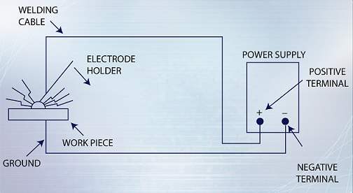
The circuit shown in Figure 3 is referred to as a reverse polarity welding circuit. In a straight polarity welding circuit, the current flows from the positive terminal of the power supply to the work piece (anode). The electrode holder is connected to the negative terminal of the power supply with a welding cable that becomes the cathode.
To understand the principle of a typical electric welding circuit, the nature of the current and the transport medium must be examined. During arc welding, the space between the electrode and the work piece is the point at which the arc is initiated and maintained. This point is referred to as the arc plasma. The welding arc is characterized as a high-current, low-voltage arc that requires a high concentration of electrons to carry the current. Negative electrons are emitted from the cathode (work piece) and flow along the negative ions of the plasma to the positive anode (electrode). Positive ions flow in the reverse direction.
The cathode, anode, and arc plasma are all areas of heat generation. Heat is mainly generated in the work piece when the positive ions strike the surface of the work piece. Heat at the electrode is mainly generated by the electrons. These electrons have been accelerated by the arc voltage as they pass through the plasma. The electrons then give up their energy as heat when they strike the electrode.
Electrode Types
Several types of welding electrodes are available for different welding processes and materials. The original welding electrode was a piece of bare metal wire, and bare electrodes are still used today. Bare wire electrodes are manufactured in 36-inch straight lengths that range in sizes from 1/16 to 1/8-inch in diameter. Bare wire electrodes are also manufactured in continuous lengths that are wrapped on spools and that range in sizes from 0.035 to 0.045-inch in diameter. Covered electrodes are very common and are readily adaptable to field welding applications. These electrodes have a bare metal rod as a core and are covered with baked-on flux that provides such functions as shielding from the atmosphere, de-oxidation, and arc stabilization. Flux can also serve as a source of metallic additions to the weld. Flux cored electrodes are similar to coated electrodes. Each of these electrodes consists of a tubular wire filled with a flux material. These electrodes are generally manufactured in sizes from 0.045-inch up to 0.063-inch in diameter.
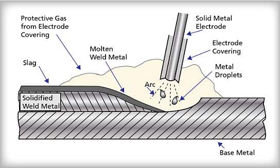
Consumable
A consumable electrode is one that is consumed in the heat of the welding arc and adds metal to the weld. Consumable electrodes are considered to be filler metal. Figure 4 shows a consumable electrode that is used for shielded metal arc welding to make a weld on base metal. As the solid metal electrode is drawn near the base metal, the electrical circuit is completed and an arc is created. The solid metal electrode is heated in the arc, and, as a result, the electrode melts. As the electrode melts, small metal droplets are transferred from the solid metal electrode to the molten weld metal. As the molten weld metal cools under the slag, solidified weld metal that is fused to the base metal is formed. When the solid metal electrode is heated and burned in the arc, the covering on the solid metal electrode forms a protective gas over the molten weld metal. Some of the electrode covering material is metallic and becomes molten weld metal. The remainder of the electrode-covering material melts and forms over the solidified weld metal a ceramic cover called slag.
As the solid metal electrode melts and becomes shorter, the consumable electrode must be continuously lowered towards the base metal to maintain the proper arc length. Ultimately, when the usable portion of the consumable electrode has melted, the arc can no longer be maintained, and melting no longer occurs. The consumable electrode has then been fully consumed and another consumable electrode must be used to continue the welding process.
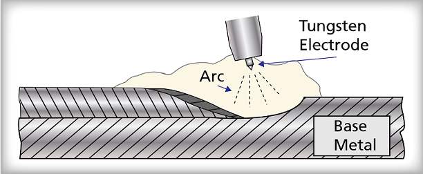
Non-Consumable
A non-consumable electrode is one that is not consumed in the heat of the welding arc and that does not provide any metal to the weld. Figure 5 shows a non-consumable electrode that is used with the gas tungsten arc welding process. As the non-consumable electrode is drawn near the base metal, the electrical circuit is completed and an arc is created. Unlike the consumable electrode, non-consumable electrodes can effectively maintain the welding arc without melting. In this case, the non-consumable electrode is made from tungsten, which melts at about 6,200oF. Although the molten weld metal may reach and exceed this temperature, the actual temperature of the non-consumable electrode is well below the melting point of tungsten.
Because the non-consumable electrode does not melt, it is very easy to maintain a constant arc length with the base metal. Welding processes that use non-consumable electrodes do not have to be interrupted to replace the non-consumable electrode. In order to deposit filler metal when a welding process that uses non-consumable electrodes is being applied, a filler metal must be added to the welding arc.
SMAW Electrodes
The electrodes used for SMAW are manufactured by having a thick flux covering surrounding a solid metal wire core. There are many variations on lengths, diameters, flux coverings, and wire core materials. The proper identification of an SMAW electrode is necessary for the welder to create a successful weld.
Classification of SMAW electrodes is based upon the metal wire core. When lengths or diameters are given for an electrode, these dimensions represent the wire core. The most common electrode lengths range from 11 to 18 inches. Common diameters come in a range from 1/16 to 3/8 inches and are available in 1/32-inch increments inside this range.
The flux covering is used to for several advantages.
These advantages include the following:
- Produces a protective gas around the weld.
- Provides fluxing elements and deoxidizers.
- Creates a solid coating (slag) over the weld as it cools.
- Establishes electrical characteristics.
- Adds alloying elements.
One problem that occurs with SMAW electrodes is that the flux covering can absorb moisture. This moisture will create excessive hydrogen during the welding process from the electrolysis of water. To prevent this occurrence, electrodes should not be exposed to an open-atmospheric condition. Storage of electrodes should be in either a drying oven or an airtight canister. The drying oven should be set for 250°F to maintain the welding electrode dry.
Selecting the Proper Electrode
Proper electrode selection is crucial in the formation of a strong weld. Selection of the proper electrode is based upon several factors. These factors are as follows:
- Experience of the welder
- Weld specifications
- Design of the weld
- Base metal to be welded
- Type of current to be used during the weld
- Penetration desired
- Thickness of the metal
- Deposit rate of the weld material
- Position of the weld
Some welding tasks will be very specific on the type of electrode to be used. If the weld task does not specify the exact electrode, the welder must rely on experience in the proper selection of an electrode.
Striking the Arc
The ability to strike an arc is one of the first aspects of SMAW to be mastered. The two most frequently used methods of initiating an arc are by using a glancing/scratching motion or a down-and-up motion. When striking the arc to the base metal, ensure that the location of the arc striking is performed where the weld bead needs to begin.
One common problem that occurs for a new welder is sticking the electrode to the base metal. This normally occurs from holding the electrode too close to the base metal. Another problem for the new welder is extinguishing the arc. This usually occurs because the welder withdraws the electrode too far away from the base metal.
At times during the welding process, the arc may continue to extinguish even if the electrode is held at an appropriate distance. This is because the current is set too low. Correction for this problem only requires a higher adjustment of the current setting. At other times, excessive spattering can occur while welding. This condition is almost always caused by having the current setting too high. Lowering the current setting will greatly reduce the amount of spattering that occurs. Care must be taken when adjusting the arc current to ensure that neither spattering nor extinguishing of the arc happens from the raising or lowering of the arc current.
Metal Identification
To become a proficient welder, the welder must obtain the ability to identify the correct types of metals. This is important for the selection of the proper electrode, weld design, and welding techniques that will be used. All metals are broken down into two groups: ferrous metals and nonferrous metals.
Ferrous metals simply are some form of metal that contains iron. Carbon steel, cast iron, and stainless steel are some examples of ferrous metals. Nonferrous metals are metals that contain no or extremely small quantities of iron. Copper, brass, aluminum, and lead are all examples of nonferrous metals.
The best way to determine the type of metal being welded is to refer to any available manufacturer’s specifications. If none are available, there are many different tests for the identification of metals. One of the quickest methods of determining whether the metal is ferrous or non-ferrous with reasonable accuracy is by using a magnet. Magnets are attracted to iron and will stick to ferrous metals. The lack of iron in nonferrous metals causes the magnet not to attach to this type of metal. Other tests include spark testing, oxyacetylene torch testing, color testing, chip testing, sound testing, fracture testing, and density testing. The welder should use the appropriate test according to the materials available for the determination of the metal material.
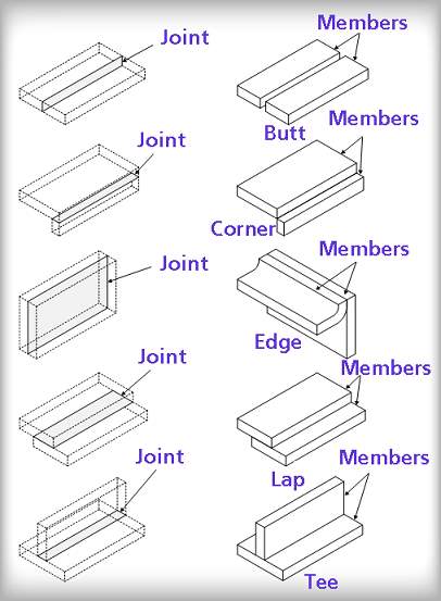
Weld Joint Description
Welds are made at the junction of at least two members. These weld junctions are called joints, which are defied as the location at which two or more members are to be joined. Parts that are joined by welding may be in the form of rolled plate, sheet, shapes, pipe, or the parts may be castings, forgings, or billets. The physical placement of the members that are to be joined defines the weld joint. Figure 6 shows the five basic types of weld joints (combination to complete a weld.
Fusion Zone
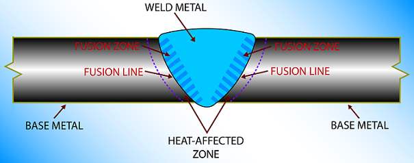
Figure 7 shows a full penetration weld joint. The fusion zone shown in Figure 7 represents the area of fusion line. The actual fusion zone can only be determined through removal of a cross-section of the weld to examine the metallurgical structure of the base metal. The depth of the fusion zone depends on the amount of heat that was input to the weld joint during welding. As more heat is input to the weld joint during welding, the size of the fusion widens. As less heat is input to the weld joint, the size of the fusion zone narrows. The heat input to the weld joint is mostly controlled by the welding voltage and the electrode travel speed.
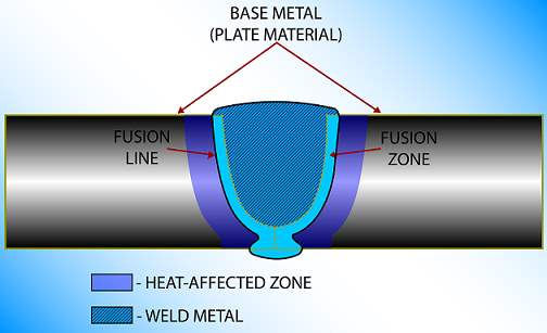
Fusion Line
The fusion line shown in Figure 7 represents the border of fusion during welding and the heat-affected zone. Beyond the fusion line, no melting of the base metal occurs.
Heat-Affected Zone
The heat-affected zone shown in Figure 7 represents that portion of the fusion zone.
Base Metal
The base metal shown in Figure 7 represents the material that is to be welded. In Figure 7, the base metal is plate material. The boundaries of the base metal include all of the material up to the HAZ. Although the area past the heat-affected zone has been heated during the welding process, changes to the microstructure and physical properties of the base metal have not occurred. However, this heat can cause warping of the base metal that could result in the improper alignment of welded components.
Weld Joint Symbols
The American Welding Society (AWS) Standard A2.4, Standard Symbols for Welding, Brazing, and Nondestructive Examination, is the standard for weld symbols. A weld symbol represents the weld joint on a drawing so that the details of the weld joint do not have to be shown. The specific weld symbols described in this section include stud. To aid in the understanding of these weld symbols, each weld symbol includes an illustration of the desired weld detail that matches the weld symbol.
Elements of a Weld Symbol
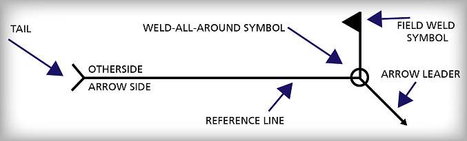
Figure 8 shows the basic components of a weld symbol including the reference line, arrow leader, tail, arrow side of the reference line, other side of the reference line, weld-all-around symbol, and field weld symbol. The reference line is the horizontal line from which all elements of a weld symbol are positioned. The arrow leader points to the joint to be welded. The tail is used only if additional reference information needs to be included. Weld symbols below the reference line are on the "arrow side," and the weld is made on the same side of the joint where the arrow leader points. Weld symbols above the reference line are on the "other side," and the weld is made on the opposite side of the joint from where the arrow leader points. Weld symbols that are placed both above and below the reference line are considered to be "both side," and the weld is made on both sides of the joint where the arrow leader points. The weld-all-around symbol means that a weld that extends around a series of connected joints must be completely welded around the entire series of connected joints. The weld-all-around symbol is not required for circumferential butt welds. The field weld symbol identifies those welds that must be made in the field.
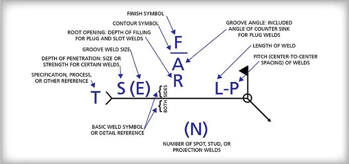
Additional elements can be added to this basic weld symbol to provide more weld joint information. To establish uniformity among all possible weld symbols, the AWS has standardized the location of these elements on a weld symbol. Figure 9 shows the standard location of elements for any weld symbol that includes the finish symbol, contour symbol, root opening, groove weld size, depth of penetration, welding procedure specification (or other reference), basic weld symbol. number of spot, stud, or projection welds. pitch. length of weld. and groove angle.
Fillet
The dimensions of fillet welds are always shown on the same side of the reference line as the weld symbol, and they generally identify the size of the weld, the length of the weld, and the pitch of the weld. Figure 10 shows a weld symbol for a 5/16 inch fillet weld on the arrow side of the joint. Figure 10 also shows the desired weld.
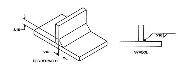
Figure 11 shows a weld symbol for a 1/2-inch fillet weld on the arrow side of the joint and a 1/4-inch fillet weld on the other side of the joint. Figure 11 also shows the desired weld.
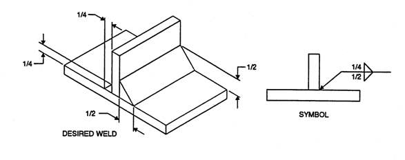
Figure 12 shows a weld symbol for a 1/4-inch (Member A) by 1/2-inch (Member B) fillet weld (unequal leg) on the arrow side of the joint. Figure 12 also shows the desired weld. Because the weld symbol convention does not provide sufficient detail, a note is required when it is necessary to accurately locate the 1/2-inch leg.
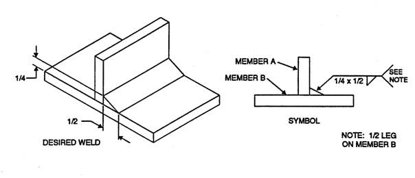
Figure 13 shows a weld symbol for a 1/4-inch intermittent fillet weld on both sides of the joint that is 2-inch long with a pitch of 5 inches. Figure 13 also shows the desired weld.
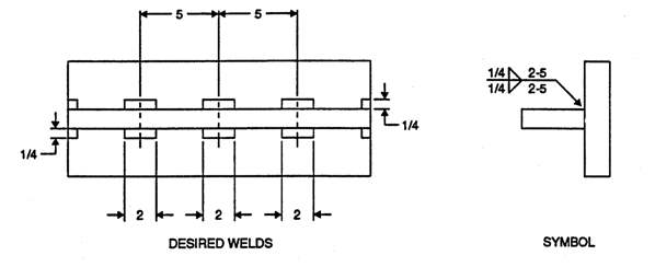
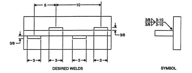
Figure 14 shows a weld symbol for a 3/8-inch staggered intermittent fillet weld that is staggered on both sides of the joint and that is 3 inches long with a pitch of 10 inches. Figure 14 also shows the desired weld.
Butt
The dimensions of butt welds are also shown on the same side of the reference line as the weld symbol. Butt weld symbols generally identify the root opening, groove angle, contour symbol, and finish symbol. Figure 15 shows a weld symbol for a single-V groove weld with zero root opening, a 60° included bevel on the arrow side of the joint, and the desired weld.
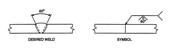
Figure 16 shows a weld symbol for a double-V-groove weld with a 1/8-inch root opening, a 60° included angle, a 3/4-inch depth of preparation, and a ground convex face. Figure 16 also shows the desired weld.
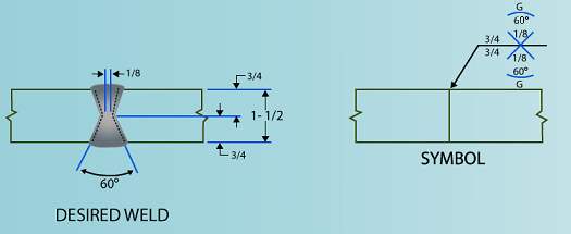
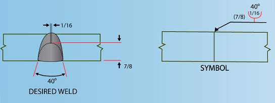
Figure 17 shows a weld symbol for a single-U-groove with a 1/16-inch root opening, a 40° included angle, and a 7/8-inch depth of preparation on the other side of the joint. Figure 17 also shows the desired weld.
Partial Penetration
The dimensions of partial penetration welds generally identify the root opening, groove angle, depth of preparation, groove weld size, contour symbol, and finish symbol. Figure 18 shows a weld symbol for a single-V-groove weld with zero root opening, a 60° included angle on the arrow side of the joint, a depth of preparation of 1/4-inch, and a weld size of 3/8-inch. Figure 18 also shows the desired weld.
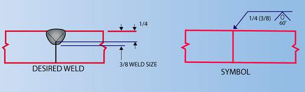
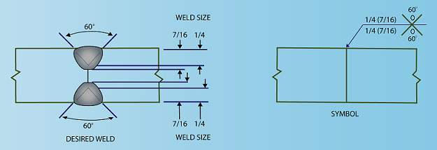
Figure 19 shows a weld symbol for a double-V-groove weld with a zero root opening, a 60° included angle, a depth of preparation of 1/4_inch, and a weld size of 7/16-inch. Figure 19 also shows the desired weld.
Combination
The dimensions of combination welds may include the root opening, groove angle, depth of preparation, groove weld size, contour symbol, finish symbol, fillet weld size, the length of the weld, and the pitch of the weld. Figure 20 shows a weld symbol for a square groove weld (both sides) with zero root opening, a weld size of 3/8-inch, and a 1/4-inch fillet weld (both sides). Figure 20 also shows the desired weld.
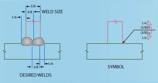
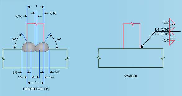
Figure 21 shows a weld symbol for a single-V-groove weld (both sides) with a zero root opening, a 60° included angle, a depth of preparation of 1/4-inch, a weld size of 9/16-inch, and a 3/8-inch fillet weld (both sides). Figure 21 also shows the desired weld.
Stud
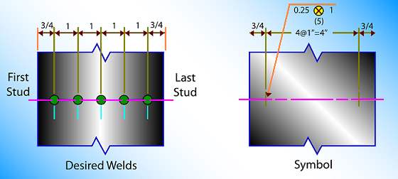
The symbol for a stud weld is a circle with a cross in the center. Figure 22 shows a stud weld symbol with a 0.25-inch stud diameter, a pitch of 1 inch, and five stud welds. The stud weld symbol does not indicate the welding of a joint in the ordinary sense; therefore, it has no arrow or other side significance. The stud weld symbol must be placed below the reference line, and an arrow must clearly point to the surface to which the stud is to be welded. As with other weld symbols, the dimensions must be placed on the same side of the reference line as the stud weld symbol. Because a stud weld symbol cannot locate the first and last stud weld, the drawing must also specify the exact location of the first and last stud welds that are in a single line. In Figure 22, the first and last studs are positioned 3/4 inch from the edges of the plate.
Weld Joint Properties
The mechanical and physical properties of materials determine which materials are considered applicable in the design of a product. In the design of weldments, the properties of primary concern are those properties that indicate the behavior of metallic materials under various conditions of loading. These properties are determined in testing laboratories, where standardized procedures and equipment are used to gather data. The adequacy of a weld depends on whether the completed weld provides properties that are equal to or exceed those of the base metals being joined.
Properly executed welds generally have mechanical properties that are superior to the mechanical properties of the base metals that were joined. The following mechanical properties will be discussed in this section:
Tensile Strength
Tensile strength is the maximum strength developed in a metal tension test. The tension test is a method to determine the behavior of a metal under an axial stretch loading. To determine the tensile strength of a weldment, two base metals are welded together, sectioned, and machined to make a reduced-section tensile specimen. Under a tensile load, the tensile specimen will exhibit elastic elongation in proportion to the applied tensile load. At the yield point, the specimen will continue to exhibit plastic elongation without an increase in the load. Ultimately, the load is increased until the tensile specimen is pulled apart and fails. The ultimate load divided by the cross-sectional area of the tensile specimen determines the actual tensile strength of the welded assembly.
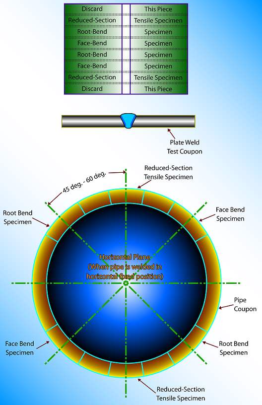
Figure 23 shows where to remove the reduced-section tensile specimens in weld test coupons. Figure 23 (A) shows the location of the two reduced-section tensile specimens in plate coupons, and Figure 23 (B) shows the location of the two reduced-section tensile specimens in pipe coupons. The reduced-section tensile specimens are located so as to provide representative tensile strength data for the entire weld test coupon.
Figure 23 also shows the location of the following specimens for purposes of reference:
- Root-bend specimens
- Face-bend specimens
Ductility
The ductility of a metal is the property that allows the metal to be stretched or otherwise changed in shape without breaking and then be able to retain the changed shape after the load has been removed. To determine the ductility of a weldment, two base metals are welded together, sectioned, and machined to make a guided-bend specimen. The guided-bend specimen is then bent in half to a specific radius that is based on the thickness of the specimen. Bending is accomplished with either a roller jig or a wrap-around jig as shown in Figure 24 . The ductility of a weldment is very important because a higher ductility indicates a weld that would be less likely to crack in service.
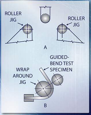
The types of guided-bend specimens used to test weld ductility include face, root, and side. A root-bend specimen is a specimen in which the root of the weld becomes the convex surface of the bend specimen; a face bend specimen is a specimen in which the face of the weld becomes the convex surface of the bend specimen; a side bend specimen is a specimen in which one of the side surfaces of the weld becomes the convex surface of the bend specimen.
Figure 23 showed where to remove transverse bend specimens in weld test coupons. Figure 23 (A) illustrated the location of the four bend specimens (two face and two root) in plate coupons, and Figure 23 (B) illustrated the location of the four bend specimens (two face and two root) in pipe coupons. The root and face bend specimens are located to provide representative ductility data for the entire weld test coupon.
Hardness
The hardness of a metal is defined as "the resistance of a metal to local indentation by a harder substance." Hardness testing is not a requirement of the fabrication codes, but it is often invoked by a job specification. Hardness data from a weldment provides an indication of the metallurgical effects of the welding process on both the weld metal and the heat-affected zone. Hardness data provides an indication of the approximate ductility of the weldment, and the ability of the metal to withstand impact loads. The hardness of a weldment is important because very hard metallic surfaces indicate a weld that would be more likely to crack in service.
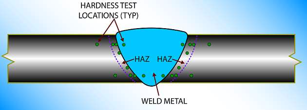
To determine the hardness of a weldment, a hardened steel ball or diamond is forced into the surface of the metal under a definite weight in a hardness testing machine. The amount of indentation is converted into a numerical value used to compare the relative hardness of a specific metallic surface. For welding procedure qualification coupons, the hardness testing must be performed on a cross-section of the weldment that has been etched to clearly show the base metal, weld metal, and HAZ, as shown in Figure 25. For production weldments, the hardness testing must be performed on the ground surface of the weld near the middle of the deposited weld bead. Additional hardness testing of the HAZ may be required by the applicable construction standard.
Impact Strength
Impact strength is the ability of a metal to absorb the energy of a load that is rapidly applied to the member. A metal may have good ductility under static loading, yet it may fracture if subjected to a high velocity impact. A material or weldment that does not have sufficient impact strength may be too brittle for the intended service. Because ductility allows the material or weldment to redistribute concentrated stresses and prevent material failures, adequate ductility is an important engineering consideration. Even if no stress concentrations are present in a brittle material, fracture will still occur suddenly because the yield stress and tensile strength are practically identical. Knowledge of the impact properties of materials and weldments is very important because a material or weldment that is ductile at room temperature can become brittle in the presence of stress concentrations, low temperature, high rates of loading, or embrittling agents such as hydrogen.
Impact strength testing is required by certain fabrication codes, such as ASME Section VIII, and it is most often determined by the Charpy V-notch test. To determine the impact strength of a weldment, two base metals are welded together, sectioned, and machined to make impact specimens. The impact strength of a material is determined by measuring the energy absorbed by the impact specimen while a weighted pendulum strikes and breaks the specimen. The absorbed energy is measured in foot-pounds. The temperature at which impact testing is performed depends on the application of the weldment. Impact testing at temperatures that are as low as -423°F (temperature of liquid hydrogen) is not uncommon.
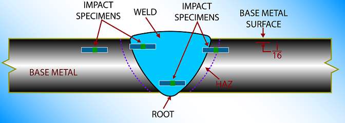
Depending on the fabrication code, impact specimens that represent the weld metal, heat-affected zone, and base metal areas may have to be tested. A set of three impact specimens is generally required from each area to adequately characterize the impact strength of the welded assembly. Figure 26 shows where to remove impact specimens in weld test coupons used for pressure vessel construction. The impact specimens are removed so that the top of the specimens are 1/16" below the surface of the base metal. In relatively thick weld test coupons, additional specimens would be removed somewhere between the root of the weld and the middle of the weld.
Metal Properties
There is no simple definition of metal; however, any chemical element having “metallic properties” is classed as a metal. “Metallic properties” are defined as luster, good thermal and electrical conductivity, and the capability of being permanently shaped or deformed at room temperature. Chemical elements lacking these properties are classed as nonmetals. A few elements, known as metalloids, sometimes behave like a metal and at other times like a nonmetal. Some examples of metalloids are as follows: carbon, phosphorus, silicon, and sulfur.
Although steelworkers seldom work with pure metals, we must be knowledgeable of their properties because the alloys we work with are combinations of pure metals. Some of the pure metals discussed in this article are the base metals in these alloys. This is true of iron, aluminum, and magnesium. Other metals discussed are the alloying elements present in small quantities but important in their effect. Among these are chromium, molybdenum, titanium, and manganese.
An “alloy” is defined as a substance having metallic properties that is composed of two or more elements. The elements used as alloying substances are usually metals or metalloids. The properties of an alloy differ from the properties of the pure metals or metalloids that make up the alloy and this difference is what creates the usefulness of alloys. By combining metals and metal-loids, manufacturers can develop alloys that have the particular properties required for a given use.
Very rarely do steelworkers work with elements in their pure state. We primarily work with alloys and have to understand their characteristics. The characteristics of elements and alloys are explained in terms of physical, chemical, electrical, and mechanical properties. Physical properties relate to color, density, weight, and heat conductivity. Chemical properties involve the behavior of the metal when placed in contact with the atmosphere, salt water, or other substances. Electrical properties encompass the electrical conductivity, resistance, and magnetic qualities of the metal. The mechanical properties relate to load-carrying ability, wear resistance, elasticity. When selecting stock for a job, your main concern is the mechanical properties of the metal.
The various properties of metals and alloys were determined in the laboratories of manufacturers and by various societies interested in metallurgical development. Charts presenting the properties of a particular metal or alloy are available in many commercially published reference books. The charts provide information on the melting point, tensile strength, electrical conductivity, magnetic properties, and other properties of a particular metal or alloy. Simple tests can be conducted to determine some of the properties of a metal; however, we normally use a metal test only as an aid for identifying apiece of stock. Some of these methods of testing are discussed later in this lesson.
Distinguishing between the Various Joining Processes
Welding
Welding is the only way to join two or more pieces of metal so that the pieces act as one piece. Welding is widely used to manufacture or repair all of the products made of metal. Almost everything made of metal is welded; some examples are the world’s tallest building, rocket engines, nuclear reactors, pressure vessels, piping, home appliances, and automobiles.
The use of welding is still increasing because it is the most economical and efficient way to join metals. Welding has become complex and technical, and it requires considerable knowledge to select the proper welding process for critical work. The many advantages of welding include the following:
- The lowest cost of joining method
- Affords lighter weight through better utilization of materials
- Joins all commercial metals
- Can be performed in any location
- Provides design flexibility
The process of welding produces localized coalescence of metals by heating the metals to a suitable temperature. Localized coalescence can occur with or without the application of base metals with the filler metal to form one weld. Filler metal is not used in all applications, and, when filler metal is absent, the welding process merely melts both base metals together.
Figure 27 shows a completed weld, which is a typical groove weld that is formed between two base metals that includes the base metal, the weld metal, the fusion zone, and the fusion line. The weld metal is a combination of melted base metal and filler metal. The fusion zones are the junction between the base metal that has melted and the unmelted base metal. Typical welding arc temperatures range from 8,500°F to 10,900°F, and steel melts at approximately 2,800°F.
The purpose of welding is to join two pieces of metal together to provide a single piece that has mechanical properties that are equivalent to the weaker of the two base metals. These mechanical properties may include tensile and compressive strength, hardness. More than forty different welding processes are available for the different applications. This section will focus on the following arc welding processes:
- Shielded metal arc welding
- Gas tungsten arc welding
- Gas metal arc welding
- Oxyacetylene welding
- Oxyacetylene torch cutting
- Air arc cutting with carbon
- Brazing
- Soldering
Shielded Metal Arc Welding
The shielded metal arc welding (SMAW) process, which is commonly called "stick" welding, is the most widely used arc welding process. SMAW is characterized by application versatility and flexibility, and relative simplicity of the equipment.
Shielded metal arc welding is a manual joining process in which coalescence of metals is produced by heat from an electric arc maintained between the tip of a covered electrode and the surface of the base metal in the weld joint. Figure 28 shows a simple schematic diagram of an SMAW welding circuit that includes the power supply, electrode holder, base metal, electric leads, and the electrode.
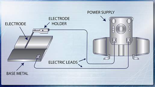
Figure 29 details the SMAW process. The figure shows the base metal, solidified weld metal, molten weld metal, slag, arc, metal droplets, electrode wire, direction of travel, electrode covering, and protective gas from the electrode covering. As the electric arc melts the base metal and electrode wire, metal droplets are transferred to the weld and become solidified metal. The electrode covering also partially melts into the weld and burns to form a protective gas.

Either AC or DC current can be used for shielded metal arc welding. To select a power supply, the following factors should be considered:
- The type of electrode to be used.
- The required amperage range.
- The welding positions.
- The availability of a primary electrical power source.
A transformer-type of power supply would be used for AC welding, and a transformer-rectifier or a motor-driven generator power supply would be used for DC welding. The motor-driven generator would have to be used in remote field applications in which primary electrical power is not readily available.
Electric leads are used to connect the electrode holder and the ground clamp to the power supply. These electric leads are generally copper cables constructed for maximum flexibility to permit easy manipulation of the electrode holder and to prevent wear and abrasion resistance. The electric leads are jacketed with a synthetic rubber that has high toughness, high electrical resistance, and good heat resistance. Because of the rugged environment of most field welding operations, the durability requirements of the electric leads cannot be overemphasized. The size of the electric leads required for a particular application depends on the maximum amperage to be used during welding and the voltage drop between the electrode holder and the power supply. As the length of the electric leads increases, the associated voltage drop through the cable also increases. To compensate for this drop, larger diameter electric leads would be required.
The device that is used to hold and control the electrode in SMAW is known as an electrode holder. The electrode holder has metal jaws that firmly hold the electrode and that conduct the welding current from the electric lead to the electrode. These jaws are covered with insulation to keep the jaws from grounding to the base metal. An insulated handle on the electrode holder separates the welder’s hand from the welding current. Electrode holders come in several different sizes to accommodate specific ranges of welding current without overheating.
The filler metal form for SMAW is a covered electrode. The covered electrode has a bare metal rod as a core and is covered with baked-on flux. Typically, this flux consists of either iron powder-low hydrogen or cellulosic materials. The electrodes are readily available in sizes that range from 3/32" to 1/4" in diameter and are from 9" to 18" in length. The size of the covered electrode is based on the diameter of the bare wire core: It is not based on the overall diameter of the covered electrode.
The purpose of the electrode covering (flux) is to perform one or more of the following functions:
- To provide a gas that prevents excessive oxygen contamination of the molten filler metal during solidification.
- To provide scavengers, deoxidizers, and fluxing agents that cleanse the weld and that prevent excessive grain growth in the weld metal.
- To establish the electrical characteristics of the electrode.
- To provide a slag blanket that protects the hot weld metal from the air and that enhances the mechanical properties, bead shape, and surface cleanliness of the weld metal.
- To provide a means to add alloying elements that change the mechanical properties of the weld metal.
Common Uses
SMAW is one of the most versatile welding processes available for use in industry. SMAW is used to perform maintenance welding operations such as the repair of defective welds, the addition of corrosion-resistant material to pressure vessel internals, and the repair of failed mechanical equipment. SMAW is readily used on carbon steel, chrome-moly steel, stainless steel, and cast iron materials in the form of plates, shapes, pipe, castings, and forgings.
The SMAW process has the following advantages:
- SMAW uses relatively simple, inexpensive, and portable equipment.
- SMAW has moderate filler metal deposition rates.
- SMAW requires relatively low skill levels for welders.
- SMAW can be used in all welding positions.
- SMAW requires no auxiliary gas shielding or flux.
- SMAW is less sensitive to wind and to drafts than are gas-shielded processes.
- SMAW is suitable for most of the commonly used metals and alloys.
The SMAW process has the following disadvantages:
- SMAW requires significant interpass cleaning to remove slag.
- SMAW has a low operating factor because of the interpass cleaning and constant addition of new electrodes.
- SMAW has limited current capability due to the diameter and length of the electrodes.
- SMAW is not applicable to low melting metals such as lead, tin, and zinc.
Running a Bead
For any welder to form a strong joint that will hold under stress from any angle or to make a satisfactory weld, the primary talent that needs to be perfected is the formation of a bead. The bead formed is the result of drawing a weld pool after the electrode. This weld pool is formed from the welding arc that is struck between the electrode and the material being welded.
There are several conditions that the welder must control in order to form a satisfactory weld bead using the SMAW method. These factors are as follows:
- Length of welding arc
- Rate of electrode movement
- Width of bead
- Angle (position) at which the electrode is held
When various electrode diameters are needed, the length of the welding arc must change accordingly. The normal arc length of covered electrodes will vary between 3/16" to 1/4". The welder needs to become proficient with welding using only one hand. There may be times when a welder must position a part with the opposite hand while tacking the piece with a weld bead.
Listening to the sound of the arc is a possible method for verifying that the arc length is correct. The welder should listen for a snapping or hissing noise. These noises are produced when there is a proper arc length. If the arc length is allowed to go below the nominal value of between 3/16" to 1/4", the arc may short out. If the arc length is allowed to go above the nominal value, excessive spattering will occur. Spattering is small solidified metal particles that are formed from the filler metal used for the weld. Even with maintaining the proper arc length, to form a good bead the welder must keep the electrode moving at a constant, forward speed. This constant forward movement is crucial to ensure a uniform height, width, and ripple spacing of the bead.
The welder has two forms of beads that can be placed on the material: the stringer or weaving bead.
- To form a stringer bead, the welder is only required to draw the bead in the forward direction. The speed of drawing the bead should be fast enough so that the weld does not burn through the material but slow enough to allow the weld pool to accumulate to approximately two to three times the diameter of the electrode. For example, if the electrode diameter is 1/4", a properly formed stringer bead will be 1/2" to 3/4" in width.
- To form a weaving bead, the welder is required to move the electrode back and forth while drawing the bead forward. Using this method, the welder is allowed to form the bead to any desired width. To maintain adequate bead control, keep the width of the bead to no more than six times the electrode diameter. For example, if the electrode diameter is 1/4", the bead should be kept to a maximum of 1 1/2" in width.
The angle at which the electrode is held should be kept tipped in the direction of travel at a 20° angle. When forming a bead, the electrode should also be parallel to the weld line.
If necessary, clean the end of the electrode and position the electrode in the holder. Strike the initial arc approximately 3/8" ahead of the location where the bead should be formed. The electrode should be moved rapidly to the location where the weld pool should begin to form. This will allow the arc to stabilize prior to the initial formation of the weld pool. With a steady arc, begin moving the electrode in a straight line in the direction of the weld line. Ensure that a 20° angle is maintained at all times. The direction of drawing a weld bead is based on personal preference. Most right-handers find it most comfortable to form a bead from left to right, while left-handed welders find a right to left motion is the most practical. Whichever direction the bead is drawn, the important aspect is a motion that feels natural and allows an unobstructed view of the weld pool. The primary reason for maintaining the electrode at a 20° angle is the arc forces the molten metal to the back of the weld pool and will allow the desired bead ripples to form.
Forward motion begins when the bead width has reached the desired size. With the desired size reached, the welder will pull the electrode slightly forward and allow the pool to grow in size again. After the proper rate of advancing the electrode has been reached, the electrode should be moved forward in one continuous motion.
Two separate factors determine the speed of forward motion of the electrode. They are:
- Desired bead width
- Formation of bullet-nose-shaped ripples in the back of the molten weld pool.
Correct height of the weld is shown by the formation of bullet-nose shaped ripples. The formation of these ripples can only be achieved by maintaining the proper forward speed. These ripples are the result of metal buildup above the surface of the metal. The welder must keep a close eye on the shape of the ripples being formed from the weld pool. If the bead takes on a pointed shape, then the speed of travel is too fast. If the bead is straight or does not have a curvature, the speed of travel is too slow.
Another good measure of how fast to move the electrode can be determined after the weld is complete. To judge this, perform the following examinations:
- The quantity of weld metal buildup
- The shape of the weld bead ripples
A properly drawn stringer bead will be even in width, height, and ripples that are bullet-nose shaped. A good rule of thumb for bead height is one quarter of the bead width.
Even while maintaining the proper speed, angle, and position of the electrode, an unsatisfactory bead can still be formed if the proper current setting is not maintained. If the current has been set too low, the bead will not penetrate the metal and will pool too high. With the current too high, the electrode will be excessively hot and will produce enormous amounts of splatter. The bead will also have too much penetration and might even burn through the metal. The resulting weld will also be extremely porous with excessive gas pockets and impurities in the bead.
Poor penetration, overlapping of the ripples, and the bead too high are indications that the arc length is too short. If the bead height is too low and there is also poor penetration and undercut, then the arc length is too large. A bead that is wide and high indicates a bead that has been drawn too slowly. Low, thin beads indicate that the forward motion was too rapid.
Restarting and Finishing an Arc Welding Bead
If an SMAW bead is stopped before it is completely finished, a deep pit will be formed in the base metal. Complete care must be taken when restarting the arc and completing the bead. When the restarting is done carefully, it will be hard to see where the bead was stopped and then restarted.
Before the welder can re-strike the welding arc, the welder must first clean the previous bead. Re-strike the arc about 3/8" ahead of the forward edge of the pit. Then move the arc quickly backward until the new weld pool touches the very edge of the rear of the first pit. As soon as the two edges come in contact, the electrode is moved forward and the welding continues. Again, if this is done carefully, the ripples of the old and new bead will match.
There are two ways to finish a bead or weld without leaving a crater. One method is to use a run-off tab. A piece of metal of the same type and thickness is tack welded to the end of the base metal being welded. The arc bead or weld is completed on the base metal and continued on the run-off tab. When the weld is stopped, the crater is on the run-off tab. The run-off tab is cut off, leaving a full-thickness bead at the end of the base metal.
A similar procedure is used to start a weld. A run-on tab is tacked to the base metal at the starting end. The welding arc is struck on the run-on tab. When the run-on tab is cut off, it leaves a well-defined, full-thickness bead at the beginning of the base metal.
By using a reverse electrode motion, the welder may also avoid a pit. As the end of the weld is reached, the electrode is moved to the trailing edge of the weld pool. The electrode is then lifted until the arc is broken when the weld pool is filled.
Cleaning the Bead
When shielded metal electrodes are used, a brittle slag coating is left, covering the weld bead. Prior to restarting a bead, this slag covering must be removed. It must also be removed after completing the bead, prior to welding over a bead, and before painting.
Many slag inclusions will result if the slag is not removed prior to restarting or welding over a bead. Slag inclusions are pieces of slag trapped or included in the weld. Slag is generally removed manually with a chipping hammer and a wire brush. The slag may also be removed mechanically by shot preening, wire brushing, or chipping.
DC Arc Blow
The AC arc is quite stable once started. The DC arc, however, may have a tendency at times to wander from the weld line. This wandering, called arc blow, is usually caused by magnetic forces around the DC electrode. All electrical conductors are surrounded by a magnetic field when current is flowing. If the current travels continually in one direction, the magnetism can become very strong. Ac electrodes are not affected because of the constantly changing direction of the current. These reversals virtually cancel the magnetic blow effects in the AC circuit.
The magnetic fields or lines of flux travel easily in metal. They move through air with more difficulty. When the arc is struck, a magnetic field is created around the DC electrode. The magnetic field prefers to travel in the base metal, not in the air. Therefore, the magnetic field forces the molten filler metal to blow inward from the end of the weld joint toward the center of the work. This is called forward arc blow. In the center area of the weld joint, the arc and molten filler metal act normally.
The magnetic flux intensifies ahead of the electrode as the welder nears the end of the joint. This happens as the magnetic flux tries to stay in the metal rather than travel out into the air. The arc and molten metal are now blown back toward the beginning of the weld. This action is known as backward arc blow. Very seldom does arc blow occur across the weld axis (sideways).
Certain preventive or corrective measures can be taken if the arc blow is extremely strong. One or more of the following may be used to correct magnetic arc blow:
- Place the ground connections as far from the weld joint as possible.
- If forward arc blow is a problem, connect the workpiece lead (ground) near the end of the weld joint.
- If backward arc blow is a problem, place the workpiece lead (ground) near the start of the weld. It also helps to weld toward a large tack weld, which gives the magnetic field a place to flow. This prevents crowding of the magnetic field. Crowding causes arc blow.
- Reduce the welding current. This will reduce the strength of the magnetic field.
- Position the electrode so that the arc force counteracts the arc blow force.
- Use the shortest arc that will produce a good bead. The short arc permits the filler metal to enter the arc pool before it is blown away. A short arc also permits the arc force to overcome the arc blow force.
- Weld toward a run-off tab or heavy tack weld.
- Wrap the electrode lead around the base metal in the direction that will counteract the arc blow force.
- Change to an AC welding machine and electrodes.
- Use the backstep method of welding.
The backstep method makes use of a number of short welds. The weld’s bead is divided into several sections. The first segment is started away from the beginning of the joint. The weld is made toward the beginning of the joint. Each section is welded back toward the previous section.
Weld Flaws and Defects
There is a wide variety of different flaws that can exist in finished welds. There are two classifications of weld flaws: imperfections and defects. Any weld flaw is referred to as an imperfection. If this flaw is visible to the naked eye, it is referred to as a defect. It is possible to see many flaws with the naked eye; however, some will require specialized destructive or nondestructive testing to detect.
Visual inspection of a weld will show the welder many serious flaws that are indicative of a poor weld. These flaws are:
- Inadequate weld proportions
- Undercutting
- Lack of penetration
- Surface flaws and defects
Welds that have the proper proportions should have a width of about three times the dimension of the electrode. Also, welds should have a ripple-shaped appearance and a slight contour or crown. Undercutting is caused by excessive penetration and will result in grooves cut along the sides (toe) of the weld bead. This is normally caused by too high of a current setting and is accompanied with high amounts of spattering. Lack of penetration is usually the result of too low of a current setting. In this weld, the weld bead overlaps the toe of the weld, and there is also little penetration. Surface flaws and defects can be any sort of spatter, cracks, holes, or pitting that can occur in the weld bead or on the base metal.
SMAW Joints
Using the SMAW process, the welder has several styles of welding techniques to use. The application of the weld style used is dependent on the joint to be used. No matter which joint is used, the proper alignment of the pieces is crucial. Maintaining proper alignment can be accomplished by the use of jigs, clamps, or by tack welding. Tack welding is the process of placing a small weld on the pieces to hold them into place. Occasionally during the application of a weld, the tack weld can become brittle and break. This can cause the pieces to shift out of alignment. To prevent this, it is recommended to place a tack weld every 3 inches along the weld path.
The different types of joints that are used in SMAW are as follows:
- Edge joint
- Lap joint
- Corner/T-joint
- Butt joint
The edge joint is a weld that is made between the edges of two or more parallel or nearly parallel parts. Edge preparation is normally only required for materials greater than 1/4 inch. During the application of an edge joint, the welder should wait to move the electrode until the weld pool comes in contact with the outside of the pieces. For thicker pieces, the welder should wait until the weld pool fills the groove prepared for the weld.
Lap joints are performed on fillet weld is usually performed to weld this joint in place. The ideal weld bead should be convex in shape. The width of the bead should reach up to the top of the edge on the one piece and extend on the face of the second piece the same amount as the weld travels up the edge. For example, if the edge piece is 1/4 inch thick, the weld should extend on the face of the second piece 1/4 inch. Several passes may be required for thicker sections of metals.
Corner or T-joints are performed when the edge of one piece rests on the face of another piece. The weld may be performed on the inside or outside of the corner. Placement of the weld will depend on application of the piece and direction of suspected stresses. Fillet welds are normally used; however, for large and wide joints, a weaving bead should be used.
Butt joints are used when the pieces are in contact edge to edge. It is recommended to prepare the edges of the metal with a V-shaped groove at a 45° angle down to within 1/16 inch of the bottom. The two pieces should be welded together with a 1/16 inch gap between to two pieces. More than one bead may be required. If additional weld beads are required, the welder needs to clean the weld prior to starting the next bead to ensure that no slag is trapped in the weld.
Gas Tungsten Arc Welding
Because of the high quality welds that are produced, the gas tungsten arc welding (GTAW) process, which is often called "TIG" (tungsten inert gas) welding, has become an indispensable welding process for many industries.
Gas tungsten arc welding can be a manual or an automatic joining process in which coalescence of metals is produced by heat from an electric arc maintained between the tip of a tungsten electrode (schematic diagram of a GTAW welding circuit that includes the power supply, torch, base metal, electric leads, filler metal, inert gas supply, cooling water supply, and water return.
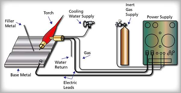
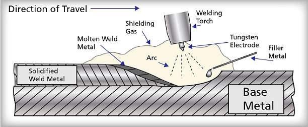
Figure 31 details the GTAW process. As the electric arc melts the base metal, the filler metal is introduced to the arc area where the filler metal also melts. After the filler metal cools, it becomes solidified weld metal. GTAW requires the simultaneous use of both hands; one hand to control the torch and one hand to control the addition of filler metal. Because of this technique, gas tungsten arc welding requires more skill of the welder. Care must be taken to ensure that the non-consumable tungsten electrode does not come into contact with the molten weld puddle. Such contact would cause the electrode tip to melt and distort.
Either AC or DC current may be used for gas tungsten arc welding. The following factors should be considered when selecting a power supply:
- The type of electrode to be used.
- The amperage range that is required.
- The welding positions.
- The availability of a primary electrical power source.
Typically, a transformer-rectifier or an engine-driven generator power supply would be used for gas tungsten arc welding. For more specific applications, such as thin sheet metal, the power supplies are equipped with a pulsed DC welding current, which results in a lower overall heat input to reduce distortion and warpage. A high frequency feature is used on some power supplies to stabilize or "stiffen" the welding arc during precision applications, at very low currents, and in outdoor areas.
Electric leads are used to connect the torch and the ground clamp to the power supply. The ground lead and the torch lead are identical to the leads used for shielded metal arc welding; however, the short torch lead also has an internal tube to convey shielding gas to the torch.
The torch that is used in GTAW holds the non-consumable tungsten electrode that conducts welding current to the arc and provides a means to convey the shielding gas to the arc zone. Torches are rated in accordance with the maximum welding current that can be used without overheating the torch. For high current (300 to 500 amps) welding applications, torches are available with a continuous flow of water through internal passageways to cool the torch. Torches are available in several different head configurations to facilitate unique welding positions and welder comfort. GTAW torches often have auxiliary switches and valves to control current and gas flow.
The filler metal form for GTAW is a bare wire. The bare wires are readily available in 36" length and in diameters that range from 1/16" to 3/16". For automatic welding applications, the filler metal is a continuous wire, as small as 0.020", wound on a spool. Extra care must be exercised to keep the filler metal clean and free of all contaminants, such as oil and moisture. Clean, uncontaminated filler metal helps to ensure high quality welds.
The purpose of the shielding gas is to provide an inert atmosphere that prevents excessive helium; however, depending on the application, argon-hydrogen and argon-helium blends are sometimes used. Argon is heavier than air, and it tends to cover the weld. Argon generally provides a smooth welding arc with adequate penetration at a low cost. Helium is lighter than air, and it does not provide adequate shielding unless the flow is significantly increased. Helium provides greater penetration of the welding arc, and it is usually preferred on thick materials.
When root passes are made on certain materials such as stainless steel and nickel-based alloys, the air on the back side of the weld joint can actually corrode the weld. To avoid this problem, the air must be purged from the root pass to prevent the formation of oxide and scale that would result in loss of passivity in stainless steel and nickel based alloys. Figure 32 shows, for a piping weld, a purge scheme that identifies the purge gas inlet, the purge gas outlet, the weld joint, and the pipe. Generally, this purge gas is the same as the shielding gas that is used in the torch, and the gas must be conveyed to the back side of the weld through a separate hose that can be regulated independently of the torch shielding gas. By flowing the purge gas into the pipe, one can force the air out through the weld joint and the purge gas outlet.
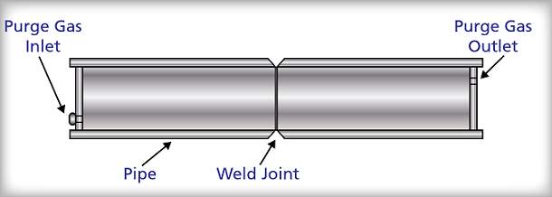
Common Uses
Because GTAW produces high quality welds, it is commonly used to weld the root pass of pipe butt welds for high alloy materials such as stainless steel and nickel base alloys. Open butt GTAW root pass welds are used on pipe to provide excellent radiographic quality welds, a smooth shallow bead contour that does not affect flow conditions, a weld that can be made from only one side, and a weld that can be made in all positions around the pipe. On thin wall materials, GTAW may be used to weld the complete joint without a significant loss of productivity. When radiographic quality welds are required on carbon steel weld joints, GTAW may also be used to ensure complete fusion of the root pass. GTAW is the process of choice for small diameter (less than 2") piping welds that include butt, fillet, and socket welds. Maintenance welding operations are performed with GTAW on small intricate parts and on materials that are very thin because of the excellent low current control of this process.
The GTAW process has the following advantages:
- GTAW provides high quality weld.
- GTAW requires little interpass cleaning.
- GTAW can be used in all welding positions.
- GTAW allows excellent control of root pass weld penetration.
- GTAW can be used with or without filler metal.
- GTAW is suitable for most of the commonly used metal and alloys.
- GTAW allows the heat source and filler metal additions to be independently controlled.
The GTAW process has the following disadvantages:
- GTAW requires relatively high skill levels for welders.
- GTAW has a relatively low deposition rate compared to consumable electrode welding processes.
- GTAW is not cost effective to use on thick sections.
- GTAW is not conducive to welding in windy or drafty areas.
Selecting the Proper Shielding Gas for GTAW
Inert shielding gases surrounding the weld area allow the GTAW to produce high-quality welds. The most common shielding gas used for AC and DC GTAW is argon (Ar). Compared to helium, argon provides a smoother, quieter arc. Argon requires a lower arc voltage and provides a better cleaning action than helium. Argon is used in AC welding because of the lower required arc voltage. Argon is ten times heavier than helium, which makes argon heavier than air. The weight of argon allows it to provide better shielding than helium, so less gas is required.
Helium (He) provides a higher available heat at the workpiece than does argon. GTAW performed with helium gas produces deeper penetration than GTAW performed with argon. This deeper penetration makes helium a better choice as a shielding gas on thicker sections of metal.
When a situation arises where deep penetration and good cleaning action are required, argon and helium gas mixtures are used. These mixtures contain up to 75 percent helium. This allows the higher available heat for the deeper welds and the better cleaning (shielding) action of argon.
The use of hydrogen (H2) to mix with argon when welding stainless steel, nickel-copper, or nickel-based alloys permits increased welding speeds. Hydrogen is not recommended for use on other metals, because it produces hydrogen cracks in the welds. Table 1 lists the shielding gases and current types for various metals. For manual gas tungsten arc welding, argon is the most common shielding gas. Argon-helium mixtures are sometimes used. When doing automatic GTAW, argon, helium, argon-helium, and argon-hydrogen mixtures are used. Gas mixtures can be obtained in cylinders from local welding gas distributors or can be mixed using a gas mixer.
|
Table 1: Shielding Gases |
|||
|
Metal |
Thickness |
Manual |
Automatic (Machine) |
|
Aluminum and aluminum alloys |
Under 1/8" (3.2 mm) Over 1/8" (3.2 mm) |
Ar1 (AC-HF) |
Ar (AC-HF) or He2 (DCEN) |
|
Copper |
Under 1/8" (3.2 mm) Over 1/8" (3.2 mm) |
Ar-He (DCEN) |
Ar-He (DCEN) |
|
Nickel alloys |
Under 1/8" (3.2 mm) Over 1/8" (3.2 mm) |
Ar (DCEN) |
Ar-He (DCEN) or He (DCEN) |
|
Steel, carbon |
Under 1/8" (3.2 mm) Over 1/8" (3.2 mm) |
Ar (DCEN) |
Ar (DCEN) |
|
Steel, stainless |
Under 1/8" (3.2 mm) Over 1/8" (3.2 mm) |
Ar (DCEN) |
Ar-He (DCEN) or Ar-H25 (DCEN) |
|
Titanium and its alloys |
Under 1/8" (3.2 mm) Over 1/8" (3.2 mm) |
Ar (DCEN) |
Ar (DCEN) or Ar-He (DCEN) |
|
1 – Ar (argon) |
Selecting the Correct Shielding Gas Flow Rate for GTAW
The flow rate is measured in cubic feet per hour (ft3/hr or cfm) or liters per minute (L/min). This flow rate varies with the base metal being welded, the thickness of the base metal, and the position of the welded joint. Higher gas flow rates are needed when welding overhead. This is necessary because argon, which is heavier than air, tends to fall away from the overhead joint.
Once the correct gas mixture and required flow rate have been determined, the flow rate needs to be correctly adjusted on the flowmeter. The most common flowmeter is the vertical tube gas flowmeter.
The supply valve for the gas cylinder must be opened before setting the flowmeter. The procedure for opening the shielding gas cylinder is as follows:
- Rotate the adjusting screw in a counterclockwise direction to close the regulator. NOTE: If a preset pressure regulator is used, there will not be an adjusting handle. Once the nut is placed over the adjusting screw. In this case, the regulator is always open.
- Slowly crack open and then fully open the cylinder valve. This is required because a back seating valve is used to seal the valve stem from leakage. A back seating valve is also used in an oxygen cylinder.
- When a regulator adjusting screw is provided, turn the adjusting screw in to achieve the pressure at which the flowmeter is calibrated. The pressure at which the regulator is calibrated at is normally posted on the regulator. The majority of flowmeters are calibrated to 50 psig.
- Press the foot pedal on thumb contactor switch to cause the shielding gas to flow to the torch.
- Turn the adjusting knob out on the flowmeter until the desired flow rate is indicated.
- Release the foot or thumb contactor switch to stop the gas flow.
Selecting and Preparing a Tungsten Electrode
Performing a successful gas tungsten arc weld requires the selection of the correct type and diameter of tungsten electrode. The types of tungsten electrodes, with their color codes shown in parentheses, are as follows:
- Pure tungsten (green)
- Tungsten with 1 or 2 percent thoria added (1 percent-yellow, 2 percent-red). These are called thoriated tungsten electrodes.
- Tungsten with from 0.15 to 0.40 percent zirconia added (brown). These are called zirconiated electrodes.
- Tungsten with 2 percent ceria (orange). These are called ceriated electrodes.
- Tungsten with 1 percent lanthana (black).
- Tungsten electrodes that do not fit into the above classifications (gray). These electrodes can have different amounts of alloys, as listed in the previous bullets, or different alloys added, or a combination of alloys.
Pure tungsten or zirconiated electrodes are favored when AC welding. These electrodes will develop a ball or hemisphere on the tip of the electrode when they are heated. The ball shape is desirable because it reduces current rectification and allows the AC to flow more easily. Ceriated electrodes will also do fairly well when used for AC welding.
To form a ball or hemisphere, set the current to DCEP. Use a clean piece of copper to strike an arc because copper does not melt easily and does not quickly contaminate the electrode. Raise the current until the tip of the electrode forms a ball about the same diameter as the electrode.
When using either a pure or zirconiated tungsten electrode, the electrode is not sharpened to a point to achieve full current capacity. Instead, a ball the same size as the electrode diameter will be produced after the arc is struck. The ball formed may be up to 1 1/2 times the width of the electrode diameter. A ball larger than 1 1/2 times the electrode diameter may melt off and fall into the weld. A ball this size also indicates that the current might be set too high. Electrodes used with AC can be sharpened to a taper, so that a smaller ball will form on the tip, which will reduce the current capacity of the electrode.
DC welding is normally done with thoriated tungsten electrodes. Thoria raises the electron emissions from a tungsten electrode. The addition of 1 to 2 percent thoria also prevents the electrode tip from forming and maintaining a ball. Thoriated electrodes and other electrodes used for DC welding are ground to a point, and the point is then blunted.
If a thoriated electrode is used with AC, it will initially form a ball on the end. While welding, the ball breaks down quickly and forms a number of small projections at the tip. These projections will cause an uncontrollable motion of the arc. Because of this, thoriated electrodes should only be used for direct current GTAW.
Electrodes that can be used for both AC and DC welding are those with ceria and lanthana added. These electrodes do not form a ball as readily as pure or zirconiated tungsten.
Tungsten electrodes of any type need to be provided protection from contaminants. The electrode should not come in contact with the base metal, the weld metal, or the filler metal while it is hot. Such contamination prevents the electrode from emitting or receiving electrons effectively, and this contamination must be removed. One way to remove the contamination is to break off the tip of the electrode and reshape it.
Oxygen, nitrogen, and dirt in the air may contaminate the hot tungsten electrode and metal in the weld area. A shielding gas is used to prevent this contamination. After the arc is broken, the shielding gas is allowed to flow over the electrode and the weld area. The setting of the timing of the shielding gas postflow is on the arc welding machine panel.
Tungsten electrodes are manufactured in sizes from 0.010" to 1/4". The most common lengths are 6" and 7". Each diameter and type of electrode has a maximum amperage associated with it. This amperage limit varies with the current, polarity, and shielding gas used.
Grinding wheels that are used for pointing tungsten electrodes should be used only for this purpose. This segregation will help to keep the electrodes free from contamination. The most recommended grinding wheels are silicon carbide or alumina oxide. Alumina oxide wheels cut slower but last longer than silicon carbide wheel. An 80-grit grinding wheel should be used for the rough grinding of the electrode tip. A 120-grit grinding wheel should perform the finish grinding. A grinding wheel having an open structure is preferred because the grinding wheel will run cooler and collect less contamination.
Grinding electrodes should be performed in a lengthwise direction. This method of grinding provides the optimum current-carrying characteristics. Always wear safety goggles when grinding.
Another method of accurately pointing a tungsten electrode is by using a flame. A very repeatable tip is created using this method.
Determine what type and thickness of metal is to be welded. After selecting the electrode diameter, obtain a collet and collet body for that electrode diameter. Thread the collet body into the GTAW torch. Place the collet into the top of the torch, and then thread the end cap onto the torch. Place the electrode into the torch collet, and tighten the end cap to secure the electrode in place.
An electrode may be installed so that it is even with the end of the nozzle. It may extend 1/2" or more. As a rule, the electrode should extend a distance equal to one to two electrode diameters but not more than the nozzle diameter. Some joints, such as corner or T-joints, require a longer electrode extension. As the electrode extension increases, higher gas flows must be used or the use of a gas lens is required.
Selecting the Correct GTAW Torch Nozzle
Nozzles used on gas tungsten arc welding torches vary in size and method of attachment. The end of the nozzle varies in design to allow for attachment to different manufacturer’s torches.
Most nozzles used for GTAW are manufactured from ceramic materials. The exit diameter is manufactured in an assortment of sizes. GTAW nozzles are also made in various lengths from short to extended nozzle.
Manufacturers have their own distinct part number for each nozzle. However, the exit diameter for any nozzle is specified with a number that represents the diameter in 1/16" increments.
The basis for the size of the nozzle is to allow coverage of the entire weld area with the shielding gas. If the exit diameter is too large or too small, poor shielding gas coverage will result.
The choice of a nozzle size is often a compromise that is necessary to meet the specific job requirements. Small-diameter nozzles are often used to permit a constant arc length. In the situation of welding a root pass, a small-diameter nozzle is used. The nozzle is constantly touching the sides of the groove as it is rocked back and forth across the root opening. It is also kept in contact with the groove opening as the weld moves forward slowly. The choice of a small nozzle diameter allows the welder to reach the bottom of the groove. It also allows the welder to keep a constant arc length.
Selecting the Correct Filler Metal for Use with GTAW
Filler metal used for GTAW is normally bare wire. The filler metal can be purchased in coils or in precut lengths. Coiled wire is cut to the preferred length by the welder. If a wire feeder is used for semiautomatic or automatic welding, the wire is fed from the coil. Precut wire is usually purchased in lengths of 24" or 36".
Filler metal alloy must be selected for the specific job. Steel welding rods are not copper-coated, as with oxyfuel gas welding because this would cause spatter and could contaminate the tungsten electrode.
Common diameters of filler wires range from 1/16" to 1/4". Smaller-diameter wire is readily available in coils to 0.015". Precut filler rods are readily available up to 1/4".
Preparing Metal for Welding
The GATW method can achieve high quality welds. Just this method alone is not enough to form a quality weld. Cleaning the surface of the base metal is required. Any oil, grease, dirt, rust, or any other material that can be trapped in a weld bead as an impurity must be removed. With increased impurities in a weld bead, fragile and imperfect welds will be formed.
There is no difference between the joint designs for GTAW and SMAW. The edge on the base metal is usually mitered or shaped to the preferred groove shape when gas tungsten arc welding metal thicker than 3/16".
Thermal or mechanical processes can be used to miter or shape the edges of the base metal. To produce clean, even, and precise cuts, plasma arc cutting is preferred. Machining, sawing, shearing, or grinding are the mechanical means normally used.
The parts of a weldment need to be secure in place prior to welding. This can be accomplished by the use of jigs or fixtures, or tack welding the pieces into place.
A backing strip or ring should be used to control the depth of penetration. The backing ring or strip may also be used when welding metals that may exhibit weakness when they reach their melting temperature. This usually occurs on such metals as aluminum, magnesium, and copper. As metal reaches its melting temperature, pieces of the metal may fall away. Large holes then form in the base metal. A backing strip or ring will help to prevent holes from forming on the metal.
On metals such as magnesium, titanium, and zirconium, a shielding gas may be applied to the backside of the metal. Application of this gas can be performed through a metal channel fastened to the backside of the weld. Filling the inside of the weldment is commonly performed on pipes or closed containers. When a closed container is welded, a vent needs to be provided. This is to prevent the overpressurization of the enclosed gases that would prevent adequate penetration.
Welding the parts in a chamber is another technique used to prevent contamination from entering the weld. Preventing the spread of contamination is accomplished by maintaining the chamber at a vacuum or filling with a shielding gas. This technique will ensure that all parts of the weld and base metal are protected. A chamber is often used to weld titanium.
|
|
CAUTION! Never enter an area filled with a shielding gas unless you are wearing supplied air breathing equipment. A person can lose consciousness in as little as seven seconds in spaces filled with shielding gases like argon. Death from suffocation has resulted. This is because shielding gases displace oxygen. |

Method of Starting the Arc
The following methods can be used to start a gas tungsten arc:
- Touch starting
- Application of a superimposed high frequency
- High-voltage starting
To start the arc, the remote finger- or foot-operated contactor switch must be depressed. This switch also causes the shielding gas to flow prior to starting the arc.
The electrode is touched to the base metal when touch starting is used, and then it is withdrawn about 1/8". The arc will stabilize after a few seconds. The arc length may then be reduced to an arc length of 1/32" to 3/32". Touching the tungsten electrode to the base metal may contaminate the weld area because of some base metal or tungsten transfer.
Touch the nozzle to the metal to initiate the arc using superimposed high frequency. The contactor switch is turned on to start the high-frequency current. A foot- or finger-operated remote switch is used as the machine contactor switch. Another technique is to hold the electrode horizontally about 1" on top of the metal when using high-frequency start. Rotate the electrode toward a vertical position. The high frequency will jump the gap to initiate the arc as the electrode comes near the base metal. The high frequency will shut off automatically when the arc is stabilized if using direct current. When using alternating current, the high frequency should remain on constantly.
A high-voltage surge is used for high-voltage starting. As in high-frequency starting, the electrode is brought close to the base metal. A high-voltage surge causes the arc to jump the gap and start when the contactor switch is pressed. The voltage surge stops automatically after the arc is stabilized.
Gas Tungsten Arc Welding Techniques
The ability to make a weld with a small heat-affected zone around it is one advantage of GTAW. Oxyfuel gas and SMAW heat a large area as the metal’s temperature is increased to the melting temperature. This creates a large heat-affected zone and possibly a weaker metal area around the weld.
Another advantage of GTAW is the absence of metal transfer through the arc. During GTAW, there is no spattering of metal globules from the welding arc or weld pool. The completed weld is of high quality, and the arc action is very quiet.
Using the lowest current necessary to melt the metal is the proper method to accomplish GTAW. The welding speed should be the highest possible that will ensure a sound weld.
The arc is directed to the area to be melted once it is struck. A molten weld pool is created under the arc, and the filler rod is added to fill the pool. When making stringer beads, the width of the pool should be about 2 to 3 times the diameter of the electrode used. A weaving bead is used if the bead must be wider. Several stringer beads may also be used to fill a wide groove joint. Sufficient shielding gas must flow to protect the molten metal in the weld area from becoming contaminated.
The filler rod must not be withdrawn from the area protected by the shielding gas. The filler rod will become contaminated if it is withdrawn while it is molten. The weld will become contaminated if the filler rod is then melted into the weld.
Heat a spot until a molten pool forms after the arc is struck. The electrode should be held at about a 60° to 75° angle from the workpiece. Hold the filler rod at about a 15° to 20° angle to the workpiece. Add the filler rod to the pool when the molten pool reaches the desired size. The electrode should be moved to the back of the weld pool when the filler rod is to be added. The filler rod is then added to the forward part of the molten pool. This technique of adding the filler metal to the weld pool may be used for all weld joints in all positions.
Shutting Down the GTAW Station
Shielding gas continues to flow for a few seconds each time the arc is broken. This protects the weld metal, electrode, and filler metal from contamination by the surrounding atmosphere. The gas also continues to flow after the torch or foot-operated contactor switch is turned off.
The GTAW torch should be hung on an insulated hook if welding is stopped for a short time. The station should be shut down when welding is to be stopped for a long period of time. Hang up the torch after the gas postflow period, and then shut off the shielding gas cylinder. Turn on the torch or foot-operated contactor switch to start the gas flow. This is done to drain the complete shielding gas system of gas. Turn out the regulating screw on the regulator to turn it off. Screw in the flowmeter to shut it off. The float ball will hit the top of the flowmeter very hard when the regulator is opened again if the flowmeter is not turned off. Turn off the arc welding power source switch.
Welding Joints in the Flat Welding Position
Welding joint designs for GTAW are the same as those used for oxyfuel gas and shielded metal arc welding. The flat or down-hand position is generally the easiest position in which to weld.
Square-Groove Weld on a Flange Joint
The metal should be bent upwards. This bent-up edge is then melted to form a weld, so no filler rod will be required. The electrode should be held at about 60° to 75° from the base metal. The GTAW arc is applied to the flanged metal to form a weld pool on both edges. The weld pool will touch the outer edges of the flange as it increases in size. The electrode must then be moved ahead to the front edge of the weld pool. The electrode is again moved ahead when the pool again touches the outer edges of the flange. This motion will become smooth and will create a weld bead with uniformly spaced ripples. This is repeated until the weld is completed.
The electrode should be moved slightly to the rear, and the contactor switch should be used to lower the welding current after the end of the weld joint is reached. Slowly raise the torch until the arc stops if remote current control is not used. Hold the electrode near the end of the weld until the shielding gas stops flowing. This post-flow of shielding gas provides protection for the weld and electrode as they cool. A rule for post-flow is to allow one second for every 10 A of current.
Fillet Weld on a Lap Joint
The fillet weld on a lap joint is tacked about every 3". An edge and a surface are being heated on a lap joint. The electrode should be aimed more toward the surface because it will take more heat to melt. Heat the metal to the melting point. The electrode is moved to the rear of the pool after the weld pool forms a C-shape. The filler metal is added to the front of the weld pool at the same time. The C-shaped weld pool indicates that both pieces are molten and flowing together. Enough filler metal is melted into the weld pool to form the desired weld bead contour. A flat or convex bead is generally desired. The filler metal is then withdrawn slightly, but it should remain within the shielding gas area. The electrode is moved to the front of the weld pool as the filler rod is withdrawn. The C-shaped pool is again formed and the filler metal added. This procedure is continued to the end of the weld. When the end of the weld is reached, the electrode is slowly raised and moved to the rear of the weld pool. Filler metal is added to fill the weld pool. The electrode is then withdrawn to break the arc, or the current is decreased until the arc stops. If a wide joint is welded, several passes may be required to fill the joint.
Fillet Weld on an Inside Corner Joint
The inside corner joint should be tack welded about every 3". The fillet weld is being made on two surfaces in this case, and each piece should be heated evenly. Therefore, the electrode should be kept at about a 45° angle to each piece. The weld pool will appear C-shaped after both pieces are melted sufficiently to run together. After the C-shaped weld pool appears, the electrode is moved to the rear of the weld pool. At the same time, the filler rod is added to the front of the weld pool. Continue to add the filler metal until a flat or convex bead forms. Withdraw the filler rod, and move the electrode to the front of the weld pool. Reform the C-shaped pool. Move the weld pool forward. When additional filler metal is required, add it to the front of the weld pool while moving the electrode to the rear of the pool. Repeat this action to the end of the weld. When the filler rod is withdrawn, always keep it within the area protected by the shielding gas. Finish off the weld by adding filler metal to fill the weld pool. Then, withdraw the torch or decrease the current until the arc stops. If a wide joint is welded, several passes will be required to fill the joint.
Square-Groove and V-Groove Welds on a Butt Joint
Edge preparation may not be required for metal under 3/16" in thickness. If full penetration is difficult to obtain from one side, the edges should be machined or flame-cut. When metals are over 3/16" in thickness, the edges must be machined or flame-cut to obtain full penetration.
If a welder performs a square-groove weld on a butt joint, the electrode should point straight down the weld line. If the electrode is pointed toward one piece or the other, that piece will melt more and the weld bead will pile up on that side. The weld joint designs used for GTAW are the same as those used for SMAW.
Except for critical applications, GTAW is seldom used to weld metals over 1/4" thick. On carbon steel, alloy steel, stainless steel, copper, and other metals over 1/4", GTAW is used only for the root pass. After the root pass is laid, other types of welding processes are generally used. Other processes used may be SMAW, SAW, and GMAW.
The design shapes may be square-, U-, J-, V-, or bevel-groove. These designs’ shapes may be cut on both sides of a thick metal butt weld. The torch and filler rod angles are the same as those used on other GTAW butt joints. Complete penetration is required in a butt weld. To obtain complete penetration, the keyhole method of welding is used.
The width of a stringer bead, like the root pass, should only be two or three times as wide as the electrode diameter. To complete a V-groove or other wide-mouthed joint, a weaving bead might be used. A weaving bead done with the gas tungsten arc should only be about six times the electrode diameter in width. If a wider area must be welded, then several narrower passes must be used.
Square- or V-Groove Outside Corner Joint
The square- or V-groove outside corner joints are welded in the same manner as a square-groove or V-groove butt weld.
Welding Joints in the Horizontal Welding Position
The welding procedures for GTAW are used when welding in the horizontal position. The weld line is horizontal, and the face of the bead is in a near-vertical position. Molten weld metal tends to move downward. The following actions can be taken to prevent this downward movement of the weld metal.
- Do not create a large-diameter weld pool.
- Add the filler rod to the upper edge of the weld pool.
- Point the electrode slightly upward. This upward angle will use the force of the arc to reduce sagging.
If a welder is welding a lap joint in the horizontal position, the angle of the electrode and filler rod with respect to the base metal surface are similar to the angles used when welding in the flat position. The electrode may be pointed upward slightly to reduce sagging of the molten metal.
Welding Joints in the Vertical Welding Position
It is important, when welding vertically, to keep the lowest current possible to make a good weld. The lower current helps to keep the weld pool from becoming too large and causing the molten metal to flow away from it. A pulsed arc may be used to provide a cooling period that will help to control the molten pool.
Electrode and filler rod angles are the same as for welding in the flat position. The electrode should be held about 60° to 75° from the base metal surface. The filler rod is held about 15° to 20° from the base metal.
Vertical welds may be made uphill or downhill. Metal thickness over 1/2" is seldom welded downhill. There is no flux to run into the molten weld pool when doing GTAW. Therefore, both uphill and downhill welding produces welds of excellent quality.
When performing a fillet weld being made on a lap joint in the vertical position, the electrode should be aimed more toward the surface. This prevents the edge of the lapped metal from melting too quickly. After the weld pool forms a C-shape, add the filler metal to it. This C-shape indicates that both pieces are molten and are running together. If the filler rod is added before the C-shaped weld pool forms, the filler metal may not fuse with both pieces of the joint. Like the fillet weld on a lap joint, do not add the filler metal until the C-shaped weld pool forms.
Welding Joints in the Overhead Welding Position
Using the gas tungsten arc, welds in the overhead position are relatively easy to make. The welder must control the temperature and size of the weld pool. This may be done by selecting the lowest possible effective current. Cooling of the weld pool is also possible by using a pulsed arc. Small beads are used to keep the weld pool small and controlled. Several passes will be necessary in this case to completely fill the weld groove. The angle of the electrode is kept at about 60° to 75° from the surface of the base metal. An angle of 15° to 20° is considered correct for the filler rod.
Semiautomatic Welding
Semiautomatic GTAW is similar to manual GTAW, with the addition of a filler metal feed mechanism. The feed mechanism must have the following:
- A wire drive device
- A speed control
- An attachment to the torch that will guide the wire into the weld pool
The welder must maintain control of the arc length and the travel speed. Semiautomatic welding is limited to relatively straight weld joints because the filler metal comes from only one direction. Changing directions is not possible unless the entire torch changes direction. This allows the filler metal to continue to enter the weld pool from the same point.
Automatic and Mechanized GTAW
Gas tungsten arc welding can be mechanized or done in a fully automatic manner. The torch is moved along the joint to be welded in mechanized and automatic GTAW. The torch may be mounted on an electrically driven tracer, on a rigid frame (as when automatic flame cutting), or a robot arm. Filler metal is added by using a wire feed motor and drive mechanism, and it is fed into the weld pool at a constant rate by the feed mechanism.
An automatic GTAW system uses feedback signals to regulate the process as required to keep a high-quality weld. Automatic GTAW usually has a voltage feedback system to control the arc voltage. The system uses the arc voltage to automatically regulate the distance of the torch to the base metal, keeping a constant arc length. To follow and track the weld seam, vision systems can be used. This is important if parts do not match up perfectly or if the joint is not a straight line. Permanent records can be kept on critical welds by videotaping the weld as it is made.
A robot using automatic GTAW can be programmed to weld a complete and complex assembly. Welding can be done in numerous positions and on different joint types with excellent results.
Mechanized GTAW does not have feedback. In mechanized GTAW, the torch is moved along a weld seam at a set height above the base metal. If the metal is not flat or the seam is not straight, there is no method for automatically adjusting the welding process.
Extremely accurate and sound welds are possible using automatic GTAW. Automatic GTAW can be used on metal as thin as 0.003". Generally, metals up to 0.02" are welded without filler rod. This is made possible by using a flange joint design and melting the flange, which serves as the filler metal. Filler wire or rod is often required above 0.02".
The filler wire feed rate must be carefully set and the wire directed into the weld pool. The wire feed rate will determine the size of the bead buildup. This allows the torch to move in slightly different directions without the need for torch rotation to keep the wire feeder in the proper location.
Automatic GTAW may be done in all positions using pulsed arc. In high-current automatic welding applications, the wire guide may be water-cooled.
To speed the rate of welding, a hot filler wire process is sometimes used. The filler wire is fed, controlled, and directed in the same manner as cold filler metal. One important difference is that hot filler wire is added to the trailing edge of the weld pool, as opposed to cold filler wire, which is added to the front or leading edge of the weld pool.
The hot wire process heats the wire before it enters the weld pool. The filler metal is resistance heated as it travels through the wire guide. This saves much of the heat of the arc for melting the base metal. Because the filler metal is preheated, the welding speed is much faster.
Gas Metal Arc Welding
The gas metal arc welding (GMAW) process, which is often called "MIG" (metal inert gas) welding, became commercially available in 1948, and it has become one of the most popular arc welding processes for efficient production welding.
Gas metal arc welding is widely used as a semi-automatic joining process in which coalescence of metals is produced by heat from an electric arc that is maintained between the tip of a base metal in the weld joint. The GMAW process uses a continuously fed consumable electrode shielded by an externally supplied gas. After the initial process settings are made by the welder (voltage, wire feed speed, and gas flow), the equipment provides for the automatic self-regulation of the electrical characteristics of the arc. The only manual controls that are required by the welder for semi-automatic operation are the travel speed, travel direction, and wire feed gun position.
Figure 33 shows a simple schematic diagram of a GMAW welding circuit that includes the power supply, base metal, electric leads, shielding gas source, shielding gas input and output, wire spool, wire feed unit, wire feed drive motor, and wire feed gun.
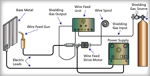
Figure 34 shows the base metal, solidified weld metal, molten weld metal, metal droplets, electrode, nozzle, direction of travel, and shielding gas. As the electric arc melts the base metal, the consumable electrode also melts and forms metal droplets. These metal droplets are transferred to the weld and become solidified metal. Because the electrode exits the wire feed gun at speeds of up to 500 inches per minute, GMAW requires excellent hand-eye coordination to maintain a consistent arc length and travel speed. Because of the speed of this process, care must be taken to ensure that complete fusion of the base metal occurs.
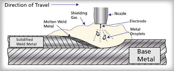
The GMAW process is capable of operating in three separate arc transfer modes. The following arc transfer modes represent subtle differences in the way in which the consumable electrode melts and is transferred to the weld puddle.
- The "short-circuiting" transfer mode is the most common mode, and it encompasses the lowest range of welding currents and electrode diameters. Filler metal (electrode) is transferred in the form of tiny droplets from the electrode to the weld when the electrode is in contact with the weld puddle. The electrode will contact the weld puddle at up to 200 times per second. The short circuiting transfer mode is limited to the use of relatively small diameter wires at current range that are below approximately 200 amperes.
- The "globular" transfer mode is similar to the short-circuiting transfer mode except that the droplets of molten filler metal will grow two to three times the diameter of the electrode before gravity causes transfer to the weld puddle. When the arc length is too short, considerable spatter will be produced. However, when the arc length is too long, the weld can exhibit lack of fusion, insufficient penetration, and excessive reinforcement. These characteristics greatly limit the use of the globular transfer mode in production applications.
- The "spray" transfer mode occurs at higher currents when at least 80% argon shielding gas is provided. The droplets of molten filler metal are smaller than the droplets in the short-circuiting mode and they spray across the arc. This mode provides higher deposition rates and greater base metal penetration. The limitations of the spray transfer mode are that it can only be used in the flat and vertical positions, and only on relatively thick materials. Also, the spray transfer mode requires the use of expensive argon gas and high amperage welding power supplies.
DC current is used for the vast majority of GMAW applications. The following factors should be considered to select a power supply:
- The required amperage range.
- The welding positions.
- The duty cycle
- The availability of a primary electrical power source.
Typically, a constant voltage transformer-rectifier or an engine-driven generator power supply that is rated for a 100% duty cycle would be used for gas metal arc welding.
Electric leads are used to connect the wire feed gun and the ground clamp to the power supply. The ground lead and the wire feed gun lead are identical to the leads used for gas tungsten arc welding. The short wire feed gun lead also has an internal tube used to convey shielding gas to the torch.
The hand-held wire feed gun used in GMAW guides the consumable electrode that conducts welding current to the arc and provides a way to convey the shielding gas to the arc zone. Wire feed guns are rated in accordance with the maximum welding current that can be used without overheating the torch and in accordance with the maximum size of filler metal that can be fed through the gun. For high current (300 to 500 amps) and continuous welding applications, wire feed guns are available with a continuous flow of water through passageways to cool the gun. For softer filler metals such as aluminum, small spools of filler that are metal-fed directly from a hand-held gun are used to improve the uniform delivery of the filler metal.
The filler metal form for GMAW is a continuous bare wire electrode. The filler metal is a continuous wire that is wound on 4" to 30" diameter spools with wire sizes that range from 0.030" to 0.125" in diameter. Depending on the nature of the welding operations, these wire spools can hold from 2 pounds to 60 pounds of filler metal. Care must be taken to avoid causing kinks and bends in the bare wire that can jam the wire feeder and halt welding operations.
The purpose of shielding gas is to provide a gas that prevents excessive cylinder. Typical gases used with GMAW are argon, helium, argon-helium and argon-oxygen blends, oxygen, carbon dioxide, argon-carbon dioxide blends, and even argon-helium-carbon dioxide blends. The gas that is used depends on the application. Factors that can affect the choice of shielding gas include the type of base metal, weld joint design, welding position, required penetration, control of heat-affected zone, and required arc stability.
As with GTAW, gas metal arc welding of root passes on certain materials, such as stainless steel and nickel based alloys, can contaminate the weld; therefore, purging operations may be required on these types of base metals to prevent contamination of the root pass.
Common Uses
Many maintenance welding applications are readily adaptable to the highly efficient GMAW process. GMAW is used in the globular and spray transfer modes to weld structural members that require a high deposition rate and that can be positioned so that most of the welding is performed in the flat position.
The GMAW process has the following advantages:
- GMAW has a high deposition rate when compared to manual arc processes.
- GMAW has a high operating factor because the filler metal is continuously fed.
- GMAW reduces interpass cleaning because there is no slag.
- GMAW (short circuiting transfer mode) can be used in all welding positions.
- GMAW is suitable for most of the commonly used metals and alloys.
The GMAW process has the following disadvantages:
- GMAW requires relatively high skill levels for welders.
- GMAW (short circuiting and globular transfer modes) has a tendency to develop lack of fusion defects due to the high welding speed.
- GMAW is more difficult to use in hard to reach places because of the size of the wire feed gun.
- GMAW can produce welder fatigue due to the high operating factor.
Inert Gases and Gas Mixtures Used for GMAW
The inert shielding gases and other gases used in shielding gas mixtures for GMAW are argon (Ar), helium (He), oxygen (O2), carbon dioxide (CO2), and nitrogen (N2).
The inert gases that are used should be welding grade gases. CO2 gas is generally supplied as 100% pure. For gas mixtures, use a gas mixer or purchase the mixture from a local welding gas distributor.
Variations in shielding gas and mixtures of gases will change the shape of the bead and the penetration of the weld.
Consider the following factors when choosing a shielding gas.
- The type of metal transfer desired: short circuiting, globular, spray, or pulsed spray transfer
- The desired bead shape, width, and weld penetration
- The required welding speed
- The undercutting tendencies of the gas
The shielding gases listed in Table 2 for short-circuiting transfer are usually also used for globular transfer. The gases listed in Table 3 for spray transfer are also used for pulsed spray transfer.
|
Table 2: Shielding Gases, Short-Circuiting Transfer |
||
|
Metal |
Shielding Gas |
Advantages |
|
Aluminum, copper, magnesium, nickel, and their alloys |
Argon and argon-helium |
Argon satisfactory on sheet metal; argon-helium preferred on thicker sheet metal. |
|
Steel carbon |
Argon Argon CO2a |
Less than 1/8" thick; high welding speeds without melt-through; minimum distortion and spatter; good penetration. Greater than 1/8" thick; minimum spatter; clean weld appearances; good weld pool control in vertical and overhead positions. Deeper penetration; faster welding speeds; minimum cost. |
|
Steel, low-alloy |
60%-70% helium 25%-35% argon Argon |
Minimum reactivity; good toughness; excellent arc stability, wetting characteristics, and bead contour; little spatter. Fair toughness; excellent arc stability; wetting characteristics, and bead contour; little spatter. |
|
Steel, stainless |
90% helium |
No effect on corrosion resistance; small heat-affected zone; no undercutting; minimum distortion; good arc stability. |
|
Table 3: Shielding Gases, Spray Transfer |
||
|
Metal |
Shielding Gas |
Advantages |
|
Aluminum |
Argon 75% helium |
0.1" – 1" thick; best metal transfer and arc stability; least spatter. 1/3" thick; higher heat input than argon. 3" thick; highest heat input; minimizes porosity. |
|
Copper, nickel, and their alloys |
Argon Helium-argon |
Provides good wetting; good control of weld pool for thickness up to 1/8". Higher heat inputs of 50% and 75% helium mixtures offset high heat conductivity of heavier gages. |
|
Magnesium |
Argon |
Excellent cleaning action. |
|
Reactive metals (titanium, zirconium, tantalum) |
Argon |
Good arc stability; minimum weld contamination. Inert gas backing is required to prevent air contamination on back of weld area. |
|
Steel carbon |
Argon |
Good arc stability, produces a more fluid and controllable weld pool; good coalescence and bead contour, minimizes undercutting; permits higher speeds, compared with argon. |
|
Steel, low-alloy |
Argon |
Minimizes undercutting; provides good toughness. |
|
Steel, stainless |
Argon
Argon |
Good arc stability, produces a more fluid and controllable weld pool, good coalescence and bead contour, minimizes undercutting on heavier stainless steels. Provides better arc stability, coalescence, and welding speed than 1% oxygen mixture for thinner stainless steel materials. |
Inert gases, such as argon and helium, are chemically inactive. This means that they do not unite with other chemical elements. Nitrogen, oxygen, and carbon dioxide are reactive gases. They will mix or react with metals in a weld. Except for CO2, reactive gases are not used alone as shielding gases.
Each gas and gas mixture has an effect on the type of metal transfer and on the bead size, penetration, welding speed, and undercutting tendencies. Each of the important gases or gas mixtures is discussed in the following paragraphs.
Argon
Argon (Ar) gas causes a compression of the arc. The results are a high current density arc, deep penetration, a narrow bead, and almost no spatter. Argon gas ionizes more readily than helium gas and does conduct some electricity. Lower arc voltages are required for a given arc length because argon does conduct some electricity. Argon gas transfers heat through the arc slower than helium. Argon also has a lower thermal (heat) conductivity. Argon is an excellent choice for use on thin metal. It is also good for out-of-position welds because of the low voltages needed.
Argon gas is the most frequently used inert gas for welding nonferrous metals. It is used for metal transfer. When using spray transfer for welding steel and steel alloys, high percentages of argon, 90 percent or greater, is required.
When pure argon is used on carbon steel, the argon will cause undercutting when using the spray transfer method. Because this undercutting is unacceptable, pure argon is normally mixed with minute amounts of oxygen or carbon dioxide.
Helium
Helium (He) has a high heat-conducting ability. Helium transfers heat through the arc more efficiently than argon does. Helium is used to weld thick metal sections. Helium is also used to weld metals that are good conductors of heat. Metals such as aluminum, magnesium, and copper will conduct heat away from the weld zone rapidly. More heat must be put into the metal when welding on these materials so helium gas is the best choice. Compared to argon, the arc voltages required for helium are higher and spatter is greater. Helium will allow filler metal to be deposited at a faster rate than is possible with argon. Helium is often used on nonferrous metals. Helium allows the formation of welds with wider bead reinforcements. When compared to argon, helium is lighter and requires a greater gas flow to protect a weld site. In addition to requiring a greater flow rate that uses more shielding gas, helium is about 10 percent more expensive than argon. Even though the cost for helium may be greater than that for argon, the benefits of helium for the right welding application makes helium an excellent choice.
Carbon Dioxide
Carbon dioxide (CO2) has a higher thermal conductivity than argon. Compared to argon, CO2 requires a higher arc voltage to be set. CO2 is a very dense gas. This characteristic allows good weld coverage and less gas to be used during the welding process. CO2 costs about 80 percent less than argon depending on location.
Beads made with CO2 have a very good contour. The beads are wide and have deep penetration and no undercutting. The arc formed in a CO2 atmosphere is unstable and a great deal of spattering occurs. Spattering can be minimized by holding a short arc. Deoxidizers like aluminum, manganese, or silicon are often added to the filler metal to remove the oxygen from the weld metal. Good ventilation is needed when using pure CO2. Around 7 to 12 percent of the CO2 becomes CO (carbon monoxide) in the arc. The amount of CO produced increases with the arc length.
Nitrogen
In Europe, nitrogen (N2) is used, where helium is not readily available. Mixtures containing nitrogen are commonly used to weld copper and copper alloys. One mixture used contains 70 percent argon and 30 percent nitrogen.
Argon-Helium
Mixtures of argon and helium help to produce welds and welding conditions that are a balance between deep penetration from helium and a stable arc from argon. A mixture of 25 percent argon and 75 percent helium will give deeper penetration with the arc stability of a 100 percent argon gas. Spatter is almost zero when a 75 percent helium mixture is used. Argon-helium mixtures are normally used on thick, nonferrous sections.
Argon-Carbon Dioxide=
Mixing CO2 in argon increases the fluidity of the molten metal in the weld pool. This helps to eliminate undercutting from using the spray transfer during GMA welding of carbon steels. CO2 also stabilizes the arc, reduces spatter, and promotes a straight-line (axial) metal transfer through the arc.
Argon-Oxygen=
Argon-oxygen gas combinations are commonly used on low-alloy, carbon, and stainless steels. A 1 percent to 5 percent oxygen mixture will form beads with penetration that is wider and less finger-shaped. Oxygen also improves the weld contour, makes the weld pool more fluid, and eliminates undercutting. Oxygen also seems to stabilize the arc and minimize spatter. Oxidation does occur with the use of oxygen, but this oxidization will normally not reduce the strength or appearance of the weld to an unacceptable level. If more than 2 percent oxygen is used with low-alloy steel, a more expensive electrode wire with additional deoxidizers must be used.
Helium-Argon-Carbon Dioxide
This shielding gas mixture is used to weld austentic stainless steel by the short-circuiting transfer method. The following mixture is commonly used for this procedure and produces a low bead: 90 percent He, 7 percent Ar, and 2 percent CO2.
Metal Transfer Methods
The various GMAW metal transfer methods and the gases suggested for use with them follow:
- Short-Circuiting Transfer – For aluminum and nonferrous metals and their alloys, pure argon, pure helium, or argon and helium mixtures are used. For carbon steels, pure CO2 or a mixture of 75 percent Ar and 25 percent CO2 is often used. To weld stainless steel, a mixture of He, Ar, and CO2 are used.
- Globular Transfer – To weld low-carbon steels with globular transfer, Ar with high percentages of CO2, or pure CO2, is used. With the use of CO2, the globules that leave the wire depart randomly and spatter is high. When argon or a high argon percentage gas mixture is used, the metal is squeezed off the wire and travels in a straighter line to the metal.
- Spray and Pulsed Spray Transfer – The spray transfer method will only occur with an atmosphere that consists of a high argon percentage. For nonferrous metals, pure argon or an argon-helium mixture is used. The following argon mixtures are used when welding low-carbon steels: argon with 2 to 5 percent oxygen (O2) and also argon with 5 to 10 percent CO2.
The use of oxygen during the spray transfer method increases the efficiency of the process. Small concentrations of oxygen will lower the transition current. Oxygen appears to reduce the surface tension of the molten metal allowing the molten metal droplets to leave the electrode easier. Oxygen makes the weld pool more fluid, reduces undercutting, and stabilizes the arc.
Table 4 lists shielding gas selections for GMAW on a number of metals.
|
Table 4: Gas Selections for GMAW |
||
|
Metals |
Gases % |
Uses and Results |
|
Aluminum |
Ar |
Good transfer, stable arc, little spatter. Removes oxides. |
|
Magnesium |
Ar |
Good cleaning. |
|
Copper (deox.) |
75He-25Ar |
Preferred. Good wetting, hot. |
|
Carbon steel |
CO2 Ar-2 O2 |
Short circuiting arc: high quality, low current, out-of-position, medium spatter. |
|
Low-alloy steel |
Ar-2 O2 |
Removes oxides, eliminates undercut, good properties. |
|
High-strength steels |
60He-35Ar-5CO2 75Ar-25CO2 |
Short circuiting arc: stable arc, good wetting and bead contour, little spatter. Good impacts. |
|
Stainless steel |
Ar-1 O2 |
No undercutting. Stable arc, fluid weld, good shape. |
|
Nickel, monel |
Ar |
Good wetting – decreases fluidity. |
|
Inconel |
Ar-He |
Stable arc on thinner material. |
Selecting the Proper Shielding Gas Flow Rate for GMAW
To ensure adequate weld coverage, enough gas must flow to create a straight line (laminar) flow. If the gas flow rate is excessive, the gas may become turbulent. Turbulence in the shielding gas will mix the shielding gas with the atmosphere around the nozzle area and cause the weld to become contaminated.
When there is inadequate gas flow, the weld area is not properly protected and will become contaminated, and porosity will occur. The manufacturer generally provides the recommended flow rate for a given nozzle. Once the correct flow rate is known, it can be used at all wire speeds. Too little gas will create a popping sound, and spatter will occur. The weld will have porosity showing, and discoloration will occur. Use the flowmeter to set the proper flow rate.
The heavier shielding gases, like CO2 and argon, tend to migrate away from the weld area when welding out of position. Therefore, the gas flow rates must be increased as the position changes from the flat to the horizontal, vertical, and overhead welding positions.
A double- or triple-unit gas mixer may be required when a gas mixture is used. A separate pressure regulator and flowmeter are provided for each gas. Premixed gas mixtures in cylinders can be purchased from welding gas suppliers, just like pure argon or oxygen.
Selecting the Correct Gas Nozzles and Contact Tubes
The end of the GMAW gun contains the gas nozzle. The nozzle is manufactured to provide the shielding gas to the weld area in a smooth, unrestricted manner. The gas nozzle is usually made of copper, which is a good conductor of heat. This characteristic will allow copper gas nozzles to resist melting when exposed to the heat generated in the welding operation.
|
Table 5: Selecting Proper Argon Flow Rate |
||||||
|
Metal |
Type Joint |
Thickness |
Weld Position |
Argon Flow |
||
|
in. |
mm |
|
ft3/hr. |
L/min |
||
|
Aluminum and aluminum alloys |
All |
1/16 3/8 3/4 |
1.59 9.53 19.05 |
F |
25 |
11.80 |
|
Stainless steel |
Butt 60° Bevel |
1/16 1/4-1/2 |
1.59 6.35-12.7 |
|
30 |
14.16 16.52 |
|
Nickel and nickel alloys |
All |
Up to 3/8 |
Up to 9.53 |
|
25 |
11.80 |
|
Magnesium |
Butt |
0.025-0.190 |
0.64-4.83 |
|
40-60 |
18.88-28.32 |
Different exit diameters are provided for the various nozzles used for modern welding applications. The correct nozzle to use for various applications is usually provided by the gun manufacturers. A general-purpose nozzle is often used and will work well for most applications.
Contact tubes, also called contact tips, are made with a variety of inside diameters (ID) and lengths. The contact tube must be designed for the diameter of electrode wire being used. A good sliding electrical contact must be made with the electrode wire. Each time the wire diameter is changed, the contact tube must be changed so that the ID matches the diameter of the wire. The electrode contact tube lies under the nozzle. The electrical connection between the welding gun and the electrode is made by the contact tube. The part of the gun called a diffuser or an adapter allows the contact tube to be threaded on to it. The diffuser threads into the welding gun. Diffusers allow the shielding gas to escape into the nozzle due to holes around the diffuser. Shielding gas exits the end of the nozzle to protect the weld area.
Most manufacturers of contact tubes make the tubes in different lengths to help to obtain different transfer methods. The longest contact tubes are normally used for short-circuiting transfer. When using short-circuiting transfer, the contact tube should be flush with the end of the nozzle or should protrude about 1/16" past the tip of the nozzle. With a long contact tube, minimal resistance heating of the wire occurs.
Resistance heating of the electrode takes place after the electrode wire exits from the contact tube. The electrode extension distance is the distance over which the electrode is heated. The longer this distance, the more heating of the electrode will take place. A long contact tube minimizes the electrode extension and reduces the resistance heating of the electrode wire.
For spray transfer, a medium-length contact tube is used. A medium-length contact tube normally maintains the tip of the contact tube inside the tip of the nozzle. This placement allows the welding current to preheat the wire to a higher temperature than when compared to the heating using a long contact tube.
For flux cored arc welding, short contact tubes are used. A flux cored electrode must be heated to a higher temperature than a solid electrode so that some of the flux will vaporize and create a shielding atmosphere around the weld. A shorter contact tube allows the electrode to be heated to a higher temperature.
Wear will occur on contact tubes, and they must be changed regularly. A contact tube can wear excessively after eight hours of continuous welding with a steel electrode. To ensure a continuous good electrical contact with the electrode wire, regular replacement of the contact tube is required.
It is important to inspect the contact tube periodically during welding operations. Inspection of the contact tube will indicate the need for replacement. When the round hole of the contact tube becomes elongated or the welding arc starts to fluctuate, the contact tube needs to be replaced. The fluctuation of the welding arc may be because of a worn contact tube not making dependable contact with the electrode.
Spattering can coat the inside and outside of the nozzle and the outside of the contact tube while arc welding. Spraying or dipping the nozzle with a special anti-stick compound can keep this spatter from sticking. The flow of shielding gas will become turbulent if the inside of the nozzle becomes spattered, and weld contamination may occur. A specific cleaning reamer is used to dislodge spatter from a nozzle.
Selecting and Installing a Liner
The electrode wire runs from the wire feeder to the welding gun in a cable. A liner, also called a conduit, is installed inside the cable. This liner prevents the cable from exposure to the continuous wear of the electrode wire. The liner also prevents the electrode wire from becoming entangled or caught while moving through the cable.
There are two types of liners. The first is a tube formed from a hardened steel wire wound in a tight coil. This wound steel liner is used for hard materials like steel and stainless-steel wires.
The second type of liner is made of Teflon. This liner is much softer than the wound steel liner material. Teflon liners are used with softer materials, especially aluminum wires.
Accumulation of fine metal filings can occur in a coiled liner. Periodically blow compressed air through the liner to remove these filings. The electrode must be removed when compressed air is used to clean the liner. When blowing out the liner, always direct the open end of the liner toward the floor or a trash can. Never allow the open end to point toward yourself or any other person. A problem also can occur if the liner ever becomes crimped, worn, or clogged. When any of these problems happens, the electrode wire will not feed smoothly, and the liner must be replaced.
To replace a liner or to change from one type to the other, use the following procedure:
- Disconnect the gun cable from the wire feeder.
- Remove the nozzle, contact tip, diffuser, and any set screws used to keep the liner in place.
- Remove the liner from the gun and cable.
- Install the new liner.
- Push the new liner firmly until it bottoms out against the far end of the cable.
- Secure the liner in place.
NOTE: Most liners are made slightly long and must be trimmed to a specific length; each manufacturer has directions to follow.
- Reassemble the welding gun.
- Attach the cable to the wire feeder.
- Re-feed the wire through the cable and liner to the gun.
Selecting the Correct GMAW or FCAW Electrode
Smaller-diameter wire usually costs more than larger-diameter wire. The rate at which filler metal is deposited when using small-diameter wire makes up for its added cost. Small-diameter electrode wire is melted quicker than larger-diameter wire because of the small diameter and the high currents generally used in GMAW and FCAW. Small-diameter wire is deposited at a much higher rate.
The welder must ensure that the electrode wire used matches, or is compatible with, the base metal that will be welded. When CO2 or O2 is used on steel-based metals, it causes oxidation of the weld metal. Deoxidizer types of electrode wires need to be used to counteract this oxidation. Manganese, silicon, and aluminum are used as deoxidizers in steel electrode wires. Titanium, silicon, and phosphorous are the deoxidizers in copper electrodes.
Once the correct electrode is selected, it should be placed in the wire feeder. The correct-size drive wheels must be used in the wire feeder. The wire should be fed through the electrode cable using the inch switch until about 2" to 3" extend beyond the nozzle.
Preparing Metal for Welding
Metal surfaces can be cleaned mechanically or chemically. Abrasive cloth or wire brushing may also be used. On severely corroded areas, grinding may be required. Welding on an oxidized (rusted) carbon steel or low-alloy steel surface may be performed without cleaning only if a deoxidizing electrode wire is used. This will reduce oxidation and weld porosity.
Joint designs for GMAW and FCAW are similar to those used for SMAW. The groove angle used when GMAW or FCAW may be smaller than the angle used when SMAW. This narrower angle is possible for two reasons. First, the wire diameters used are smaller. Secondly, GMAW penetrates better than SMAW. A 45° groove angle will take less filler metal to fill than a 75° groove angle. Welding time will also be less, which results in savings in filler metal and welder’s time.
Electrode Extension
Electrode extension is the amount that the tip of the electrode wire sticks out beyond the end of the contact tube. This distance is sometimes referred to as stickout.
An adequate extension for the electrode during the short-circuit GMAW transfer method is around 1/4" to 1/2". The correct electrode extension for all other transfer methods varies between 1/2" and 1". An electrode extension used for gas-shielded FCAW may vary from 1/2" to 1-1/2". The recommended electrode extension for use with self-shielding FCAW is 3/4" to 3-3/4".
Contact tips are made in different lengths to help to establish the correct electrode extension. Longer tips are used for short-circuiting transfer; shorter tips are used for spray transfer and FCAW.
The resistance heating of the electrode increases as the electrode extension increases. Resistance causes the current to heat the wire along the electrode extension distance. A long extension may cause too much filler metal to be deposited with low heating by the arc. This may cause spatter, shallow penetration, and a low weld bead shape.
Welding Procedures
Before starting a welding job, the welding station should be checked for safety. All electrical, gas, and water fittings must be checked to ensure they are tight.
Weldments need to be tack welded or placed into fixtures prior to welding. When complete joint penetration is needed, backing is often recommended. Backing controls the penetration and is usually in the form of a backing plate, strip, ring, or other design.
Most arc welding processes direct the welder to manipulate the arc length, welding speed, and torch or gun angle to obtain a good weld. In GMAW and FCAW, the arc length is determined by the arc voltage and will remain constant. The welder doing GMAW must watch and control the distance from the nozzle or contact tube to the work. The welder will control the electrode extension distance by controlling the nozzle-to-work distance.
The welding speed will be regulated by the formation of the bead width and penetration. Torch angle will also influence the bead width and penetration. The terms "forehand," "backhand," and "perpendicular" welding are used.
In forehand welding, the tip of the electrode points in the direction of travel. When backhand welding, the electrode tip points away from the direction of travel. Perpendicular welding is done with the electrode at 90° to the base metal.
The backhand method will give the best penetration. A 25° angle forward of perpendicular will give the best penetration in the flat welding position. For the best control of the weld pool, an angle of 5° to 15° forward of perpendicular is preferred for all positions.
To begin welding, angle the top of the gun 5° to 15° in the direction of travel, and lower the helmet down over your eyes. To initiate the arc, the wire feeder and the gas, pull the trigger on the gun. The wire will arc when it feeds out far enough to touch the metal. No striking or up-and-down motion is necessary to start the arc as required with SMAW.
As the weld pool reaches the proper width, which will occur rapidly, the welder moves the welding gun forward. Continue to move the gun along the weld, observe the width of the weld pool to keep a uniform size. Follow this technique until the end of the weld is reached. A run-off tab is recommended to ensure a full-width bead at the end of the weld. Without a run-off tab, the end of the weld may have a crater (depression). This depression can be minimized by moving the electrode to the end of the weld and then back over the completed bead about 1/2". At the end of this reverse travel, the contactor switch is released. To shield the end of the weld, hold the gun in position to allow the gas postflow to protect the weld until it cools.
Additional passes may be required to fill a weld groove. Each pass should be cleaned before the next pass is performed. This is generally done with a wire brush or wheel. The glass-like coating on some gas metal arc welds is easily removed. The slag layer on a flux cored arc weld is heavier and requires more effort to remove.
Out-of-position welds require that leathers be worn. Molten base metal, filler metal, and spatter may fall on the welder. Protection against burns, such as a cap, a coat, a cape, and chaps, should be worn.
Shutting Down the Station
When welding is secured for an extended period, the station should be shut down. To secure the station, proceed as follows:
- Return the wire speed to zero.
- Turn off the wire drive unit.
- Turn off the shielding gas cylinder(s).
- Squeeze the gun trigger, and hold it in for a few seconds to bleed the gas lines.
- Turn the flowmeter adjusting knob(s) in to close it.
- Turn off the power switch on the arc welding power source.
- Hang the gun on an insulated hook.
- Turn out the pressure adjusting knob on the flowmeter regulator, if an adjustment knob is provided.
Welding Joints in the Flat Welding Position
The face of a weld made in the flat welding position should be horizontal or close to horizontal. The weld axis should also be horizontal. Any of the metal transfer methods may be performed in the flat welding position. The method used will depend on the metal thickness and other factors.
Fillet Weld on a Lap Joint
The metal should be tack welded about every 3". Tack welding will hold the metal in position while the weld is made. Make the fillet weld by holding the centerline of the electrode at about 45° to the edge and metal surface.
If the edge begins to melt too quickly, the electrode should be pointed more towards the surface. The electrode and gun should be held between 5° to 15° forward from a vertical line to the metal surface.
Reverse the direction for about 1/2" when the end of the weld is achieved. This movement will help to minimize the crater that forms if the weld is stopped at the end of the joint. A run-off tab completely eliminates the crater at the end of the weld.
Filet Weld on an Inside Corner Joint
Edge groove preparation is not required for fillet welds made on metal up to 3/8" thick. This can be done with the spray transfer method due to the deep penetration achievable. The centerline of the electrode needs to be held at 45° to each metal surface. If the backhand welding procedure is used, the electrode and gun are held between 5° and 15° forward of vertical. GMAW can generally weld 1/4" beads on each pass. Two or more weld passes will be necessary if the weld size is greater than 1/4" thick.
Groove Weld on a Butt Joint
Edge shaping is not necessary for square-groove welds made on metal up to 3/8" thick. The GMAW process can be used for groove welds on shaped edges of any thickness. The groove angle on a V-groove butt weld can be narrower than that used with SMAW. The root face can be larger because of the penetration possible with spray transfer methods. The root opening can be smaller with GMAW than the opening used for SMAW.
The centerline of the electrode should be directly over the axis of the weld. An angle of between 5° and 15° forward of vertical is correct for the backhand welding method.
Complete penetration is occurring when a keyhole in the weld pool is developed. Whiskers are one problem that may occur in a groove weld made with GMAW. Whiskers are lengths of electrode wire that stick through the root side of a groove weld. Whiskers happen when the electrode wire advances in front of the weld pool. The wire goes through the weld root, becomes burned-off, and is then left stuck in the weld. Slowing the welding speed or reducing the wire feed speed can prevent whiskers. A small weaving motion may be used to keep the wire from getting ahead of the weld pool.
Groove Weld on an Outside Corner Joint
The outside corner joint is set up as shown in Figure 35. A square- or prepared-groove weld may be used. The electrode angles are the same as those used for welds made on a butt joint. Since groove welds are made on the outside corner joint, whiskers can occur.
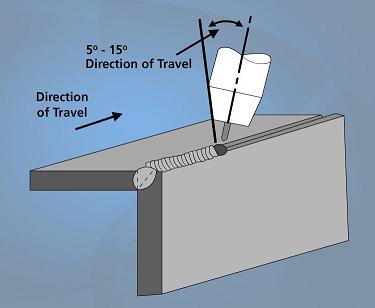
Welding Joints in the Horizontal Welding Position
The face of a weld made in the horizontal welding position is in the vertical or near-vertical welding position. In the horizontal welding position, the centerline of weld axis runs in a horizontal or near-horizontal line, as shown in Figure 36.
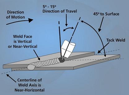
When welding horizontal butt welds. The weld pool is often too large and fluid when using spray or globular transfer.
Fillet Weld on a Lap Joint
The centerline of the electrode should be about 45° to the edge and metal surface. Point the electrode more towards the surface if the edge melts too quickly. The electrode or gun should tip about 5° to 15° forward of vertical in the direction of travel. The typical C-shaped weld pool indicates that both the edge and surface are melting correctly.
Fillet Weld on an Inside Corner or T-Joint
Square or prepared-groove welds may be formed in the horizontal welding position. The use of a V-, bevel-, U-, J-type prepared grooves will depend on the metal thickness and joint design. The bead width used in GMAW does not have to be as wide for the same thickness as when doing SMAW. This is because the gas metal arc weld penetrates more and does not need bead width and reinforcement to strengthen the weld.
The electrode should be held at 45° to each metal surface. The bead shape may be improved by aiming the wire more toward the vertical surface. This compensates for the molten metal sag. Include the gun and the electrode about 5° to 15° forward of vertical.
Groove Weld on a Butt Joint or Outside Corner Joint
A square- or prepared-groove weld may be used. The electrode centerline should be directly over the weld line. The electrode should tip 5° to 15° in the direction of travel for the best weld pool control. To keep the molten metal from sagging, the gun and electrode should also point upward slightly. Allow the molten weld pool to cool slightly by using the short-circuiting transfer and pulsed spray transfer.
Watch for a continuous keyhole through the root pass to ensure complete penetration. More than one pass is necessary on thicknesses above 3/16". An electrode weaving motion may be required to completely fill the groove.
Welding Joints in the Vertical Welding Position
GMAW in the vertical welding position is performed using the short-circuiting or pulsed spray transfer method. Spray transfer can also be used but only with small-diameter wire and a small molten weld pool. The weld axis and the weld face are both vertical in the vertical welding position.
GMAW may be made uphill (from the bottom up) or downhill (from the top down). Downhill welding is more difficult with FCAW. The flux material might flow into the weld pool and can be avoided if the welder can keep the weld pool ahead of the molten flux.
The centerline of the electrode should be tipped 5° to 15° in the direction of travel, as in other position welds. Maintaining this angle will allow the easiest weld pool control. The weld pool remains relatively cool when the short-circuiting method of metal transfer is used. A properly adjusted pulsed spray arc will allow time between pulses for the weld pool too cool. Spray arc transfer can be used in some applications, but the weld pool must be kept small. A higher travel speed must be used to maintain a small weld pool. The short-circuiting method of metal transfer keeps the weld pool coolest.
Fillet Weld on a Lap Joint
The angles of the electrode and gun are the same as for other positions. The electrode should tip about 5° to 15° in the direction of motion. The centerline of the electrode should be at about 45° to the edge and the flat surface. Point the electrode more toward the flat surface if the edge of the metal melts too rapidly. Be certain that both the edge and surface are melting completely as the filler metal is added. The appearance of a C-shaped molten weld pool indicates good fusion.
=Fillet Weld on an Inside Corner Joint=
The centerline of the electrode should be held at 45° to each surface. It should be tipped at 5° to 15° in the direction of motion. A C-shaped weld pool indicates that good fusion is occurring. Short-circuiting and pulsed spray transfer are best suited for vertical welding. Spray arc can be used with a waving motion in some applications.
Groove Weld on a Butt or Outside Corner Joint
The electrode centerline should be directly above the weld line. The electrode and torch should be inclined (tipped) 5° to 15° in the direction of travel. A keyhole at the root of the weld will indicate complete penetration.
Oxyacetylene Welding
Oxyacetylene welding (OAW) is a type of oxyfuel gas welding (OFW) that uses acetylene as a fuel gas and gaseous oxygen to support combustion to create a heating medium. The wide field of applications, as well as the convenience and economy of oxyacetylene welding, are recognized in most metal working industries. OAW is universally used and accepted in the field of maintenance and repair where the flexibility and mobility of this process results in reduced time and labor expenses.
The OAW process involves melting the hoses, gas control valves, welding torch, welding tip, and flame.
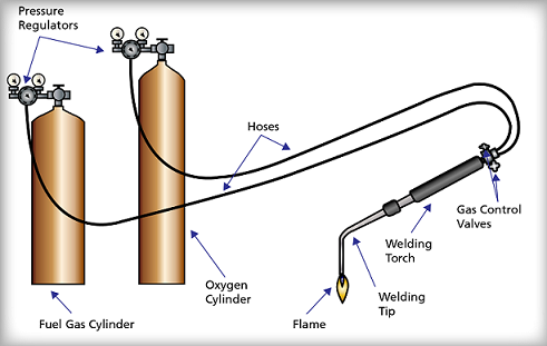
Figure 38 shows the base metal, the molten weld metal, the solidified weld metal, the flame, the filler metal, the torch tip, and direction of travel. As the combustion flame from the welding torch tip is brought into contact with the base metal, the base metal begins to absorb the heat and melt. When a pool of molten metal is established, filler metal can be introduced into the flame to melt the filler metal and to add filler metal to the weld. The weld metal becomes solidified weld metal as the weld cools.
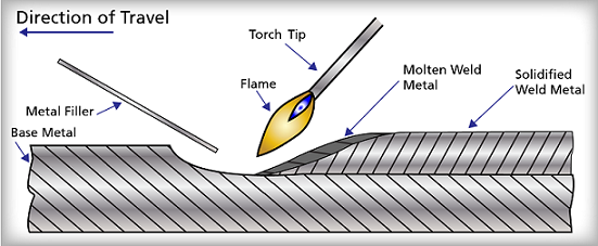
All fuel gases require oxygen to support combustion. Fuel gases that are suitable for welding operations must have a high flame temperature, a high flame rate propagation, adequate heat content, and a minimal chemical reaction between the flame and the base and filler metals. Acetylene most closely meets all of these requirements. When acetylene and oxygen are brought together and mixed, the fuel is readily ignited by an ignition source such as a striker. By controlling the ratio of acetylene to oxygen, the nature of the combustion flame can be altered to provide either a neutral flame (an equal ratio of the two gases), a carburizing flame (excess acetylene), or an oxidizing flame (excess oxygen). For most welding applications, the neutral flame is preferred.
Typical OAW applications use local gas pressure that is supplied to the welding torch and to adjust the gas flow rates.
A typical welding torch consists of a torch handle, mixer, and tip assembly. The torch can independently control the flow of each gas, accept a variety of welding tips, and control the movement and direction of the flame. The gases flow through control valves in separate passages in the torch handle to the torch head. The gases then flow into a mixer assembly in which the oxygen and acetylene are mixed. The gases finally flow out through an orifice at the end of the tip. Sealing rings or surfaces are provided in the torch head or on the mixer seats to facilitate a leak-tight assembly. Torch tips come in a variety of sizes to provide various flame sizes that are required for different materials and thicknesses.
The filler metal form for OAW is straight bare rods. The filler metal is usually manufactured in 24" and 36" lengths and is readily available in sizes from 1/16" to 3/8" in diameter. To ensure high quality welds, extra care must be exercised to keep the filler metal clean and free of all contaminants, such as oil and moisture.
The OAW process has the following advantages:
- OAW requires no electric power supply.
- OAW can be used in all welding positions.
- OAW provides excellent control of heat input and temperature.
The OAW process has the following disadvantages:
- OAW has low deposition rate.
- OAW requires relatively high skill levels for welders.
- OAW is not efficient for large welding jobs.
Oxyacetylene Torch Cutting
While oxyacetylene welding may have "taken a back seat" in industry (significantly in repair work), the use of oxygen cutting has expanded in every decade since 1902. The cutting torch has many applications, from the steel mill to the scrap yard, where steel is reclaimed and used in making more steel. Oxygen cutting is not an exclusively oxyacetylene process; other fuel gases are also widely used. However, more cutting torches are operated with acetylene than with all other fuel gases combined. The amount of oxygen consumed in cutting operations exceeds by many times the amount consumed in gas welding.
Oxygen cutting, also referred to as flame cutting, burning, or torch cutting, is frequently used to:
- Cut metals to a desired size or shape
- Cut bevels for weld joint edge preparation
- Gouge or groove metal surfaces
- Pierce holes or cut sections out of the middle of metal sheets
- Remove rough areas or surface defects from metal ingots and bars
Oxygen cutting can also be used to cut away rivets or "break" welds when dismantling a metal assembly or structure.
The equipment and accessories for oxyacetylene cutting are the same as for oxyacetylene welding except a cutting attachment (torch and tip) is used instead of a welding torch. Metal is severed or removed in oxygen cutting, rather than joined or added as in welding, but otherwise the two processes are similar.
Equipment setup, adjustment, and operation are the same for oxyacetylene cutting and welding. The cutting torch, like the welding torch, is ignited with a sparklighter.
Preheating a spot on the base metal until it is red-hot starts the cutting process. Then a jet of pure oxygen is introduced, and metal in the path of the jet is burned away. The process is a chemical reaction called oxidation. When oxidation takes place, it is called rusting. Extremely rapid oxidation is called combustion or burning. In oxyacetylene cutting, the oxidation is very rapid; the metal is actually burned away.
Only the metal directly in the path of the oxygen jet is oxidized. As the cutting flame is advanced, it makes a narrow slit, or kerf, in the metal. The kerf is just like the slit left by a saw in cutting wood. Most of the metal removed from the kerf is burned away by oxidation. The remaining materials, including slag and impurities, are blown or washed out of the kerf by the pressure or force of the oxygen jet. The burning and cutting action of the oxygen jet does not always produce sufficient heat to keep the reaction going; therefore, the oxyacetylene flame must continuously preheat the metal just ahead of the jet.
The rapid oxidation of the metal is a vital part of oxyacetylene cutting. Metals, such as iron and low-to-medium carbon steels, are easily cut because they oxidize readily, and their oxides melt at temperatures below the melting point of the base metals. Cast iron, stainless steel, high-carbon steel, and some nonferrous metals have oxides with high melting points. With such metals, it is difficult to cut a straight, uniform kerf. These problems can be minimized by thorough mechanical and/or chemical cleaning and by applying special cutting techniques.
Oxyfuel Cutting
Severing metal by the oxygen process is possible because of the reaction of metal to oxidation. For example, when a piece of iron or steel is exposed to atmospheric conditions, a reaction known as rusting takes pace. This rusting is simply the result of the oxygen in the air uniting with the metal, causing it to gradually decompose and wear away. This action is very slow, but if the metal is heated and permitted to cool, heavy scales form on the surfaces, showing that the iron oxidizes much faster when subjected to heat. If a piece of steel were to be heated red hot and dropped in a vessel containing oxygen, a burning action would immediately take place.
To make the rapid cutting of metal possible, it is necessary to have a device that heats the metal to a certain temperature and then throw a blast of oxygen on the heated section. The cutting torch, whether manually or machine operated, functions in that way.
Oxygen cutting can be used on plain carbon steels, low-alloy steels, manganese steels, and low-continent chromium steels. Nonferrous metals and stainless steels or steels with a high chromium or tungsten content that form refractory oxides cannot be cut with the oxygen process.
The Cutting Process
The process of cutting metal is an operation that occurs in separate stages. There are two main stages in the cutting process, and each is equally important. An incomplete accomplishment of either stage will result in either the inability to cut the metal or an unsatisfactory cut line. The two main phases are preheating and cutting.
Preheating the metal is necessary to raise the temperature of the metal to the ignition point. The ignition point is the temperature at which the introduction of a fuel source will burn. The fuel source that will be introduced is oxygen. Once the metal has been heated to the appropriate temperature, the cutting process begins. The best way to understand the actual physics behind cutting a section of metal is to imagine the metal as a layered substance. Introduction of oxygen to the layer of metal that has been heated to the ignition point will cause this layer to melt. The act of melting this first layer will cause the metal directly below the melted layer to rise in temperature. Once this second layer has increased in temperature, it will also melt once exposed to the oxygen from the torch. This process of melting the top layer and the transfer of heat to the layer directly beneath is progressive and will allow the severing of even thick sections of metal.
The two biggest factors affecting metal cutting are the flowrate of oxygen and the speed of the cut. Too much oxygen will cause excessive heating. This will cause excessive blow-off and curved walls. Insufficient oxygen will prevent complete severing of the metal. The amount of drag is also an important consideration. Drag is the distance between the point where the oxygen stream enters the top of the metal and the point where the slag emerges from the bottom of the metal, as shown in Figure 39. Excessive drag will cause inadequate cutting and will leave uncut corners. The amount of drag that should be present in a cut depends on the oxygen supply. If there is a lot of cutting to be performed and the oxygen supply is limited, then the cutting process will have to occur with above-normal drag.
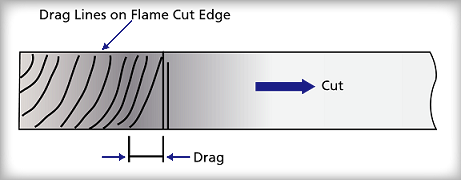
Too long a drag will leave uncut corners and cause the steel fire to extinguish before the kerf (i.e., the cut made by the cutting torch) reaches the bottom of the workpiece. When the supply of oxygen is too high, the top edges of the kerf usually burn over, producing rough surface edges and a considerable waste of oxygen. Refer to Figure 40.
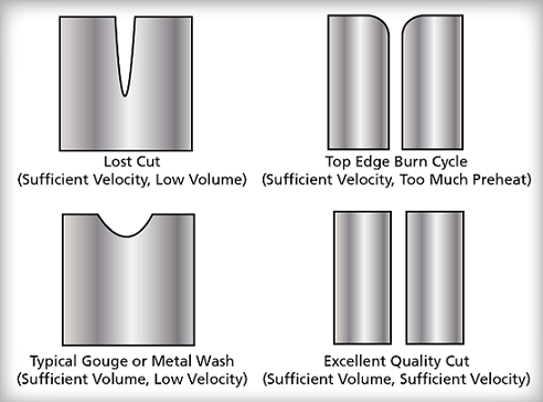
The use of correct tip size is important in cutting because it affects the speed, the accuracy, and the economy of the cutting process. A tip that is too small will fail to generate sufficient kindling temperature to keep the cutting progressing forward. If the tip size is too large, the waste of oxygen becomes extremely high.
Fuel Gases
The function of the fuel gas is to raise the temperature of the metal to start and continue the cutting operation. Several types of gases are used for this purpose. The most common are acetylene, propane, Mapp, and acetogen. The type of fuel gas selected depends on such factors as cost of gas, ease of handling gas containers, heat intensity of the flame, type of cutting to be done, and kind of metal to be cut. Table 6 lists the flame temperatures of different fuels for cutting purposes. Special tips must be used with each type of fuel gas.
|
Table 6: Fuel Flame Temperatures |
|
|
Fuel Gases |
Flame Temperature |
|
Acetylene |
5,420°F |
|
Propane |
5,190°F |
|
Hydrogen |
4,600°F |
|
Mapp |
5,301°F |
|
Acetogen |
5,400°F |
|
Natural Gas |
5,000°F |
Manual Cutting
The cutting torch is equipped with a special level for the control of the oxygen and a cutting tip that has an orifice in the center surrounded by several smaller ones, as shown in Figure 41 and Figure 42.
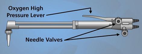
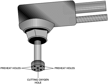
The center opening permits the flow of the cutting oxygen, and the smaller holes are for the heating flame. Tip size will depend on the thickness of the metal to be cut. Table 7 includes the various tip sizes for different thicknesses of metal as it applies to a particular cutting torch.
|
Table 7: Cutting Torch Tip Sizes |
|||
|
Tip No. |
Thickness of Metal (inches) |
Acetylene Pressure (pounds) |
Oxygen Pressure (pounds) |
|
0 |
1/4 |
3 |
30 |
|
1 |
3/8 |
3 |
30 |
|
1 |
1/2 |
3 |
40 |
|
2 |
3/4 |
3 |
40 |
|
2 |
1 |
3 |
50 |
|
3 |
1 1/2 |
3 |
45 |
|
4 |
2 |
3 |
50 |
|
5 |
3 |
4 |
45 |
|
5 |
4 |
4 |
60 |
|
6 |
5 |
5 |
50 |
|
6 |
6 |
5 |
55 |
|
7 |
8 |
6 |
60 |
|
7 |
10 |
6 |
70 |
Air Arc Cutting With Carbon
Because arc-cutting processes rely on arc heat to melt a path through metal, they can cut non-ferrous and ferrous metals. Like welding, the arc is established between an electrode that forms one terminal of an electric circuit and the work piece that forms the other terminal. The method used to flush the molten metal from the cut depends on the type of cutting.
Air arc cutting with carbon is fast and efficient for the simple removal of metal, for cutting weld grooves, or for back-gouging roots of welds. The electrode holder can direct a jet of compressed air in line with the electrode to blow away the molten metal.
Brazing
Brazing is a group of joining processes that produces coalescence of materials by heating the base metal to a suitable temperature and by using a filler metal that has a liquidus above 840°F and below the solidus of the base metal. The many joining processes include torch brazing, furnace braxing, induction brazing, resistance brazing, dip brazing, and infrared brazing. The filler metal is distributed between the closely fitted surfaces of the joint by capillary attraction. Unlike welding, the base metal does not melt during brazing to create fusion between the base metal and filler metal. There is a process that is called braze welding, which is different from brazing because, in braze welding, the filler metal is not distributed by capillary attraction.
Completed Braze Joint
Figure 43 shows the base metal, the braze filler metal, the interface gap, and the overlap. This braze joint is typical of a copper piping connection between two pipe sections and a coupling. Notice that a slight gap exists between the two pipe sections to allow for thermal expansion when the joint is in service. The joint overlap distance must be equal to 4T, where T is the thickness of the brazed joint, or as specified by the design.
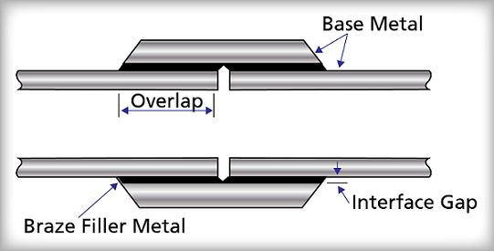
The distortion due to heating can be tolerated.
Typical Interface Gaps
In order to obtain the maximum strength from a brazed joint, the interface gap must be large enough to permit both entry of the molten filler metal and the escape of molten flux and gases during heating. When an interface gap that is too large is used, the filler metal will not be held in the joint by capillary attraction. Ideal interface gaps for production brazing are 0.002" to 0.005." Gaps as large as 0.008" can be adequately brazed.
Soldering
Soldering is a group of joining processes that produces coalescence of materials by heating the base metal to a suitable temperature and by using a filler metal that has a liquidus that does not exceed 840oF and that is below the solidus of the base metal. The many joining processes include torch soldering, dip soldering, furnace soldering, infrared soldering, iron soldering, resistance soldering, induction soldering, and wave soldering. The filler metal is distributed between closely fitted surfaces of the joint by capillary attraction.
Figure 44 shows the base metal, the solder, the interface gap, and the overlap. This solder joint is typical of a connection between two electrical connectors. Notice that the solder joint is similar to the brazed joint.