The electric motor is the workhorse of the modern industry. Its functions are almost unlimited. To control the motors that drive machinery and equipment, we must have electrical supply circuits that perform certain functions. They must provide electrical current to cause the motor to operate in the manner needed to make it perform its intended function. They must also provide protection for the motor from adverse mechanical and electrical conditions. These functions are frequently combined within the electrical equipment that we classify as motor control centers.
A thorough understanding of the function of the various components of a motor control center is desirable from both a maintenance and a troubleshooting standpoint. Properly maintained motor control centers ensure a minimum of downtime for unscheduled repairs, increase productivity, and contribute to a safer working environment.
Terms and Definitions
Before studying the aspects of electric motor control, it is necessary to first study motors. Understanding the basic principles of operation, terms, definitions, and nameplate information is the cornerstone of motor control fundamentals.
Ampacity – The current in amperes that a conductor can carry continuously under the conditions of use without exceeding its temperature rating.
Branch Circuit – The circuit conductors between the final overcurrent device protecting the circuit and the outlet(s).
Circuit Breaker – A device designed to open and close a circuit by non-automatic means, and to open the circuit automatically on a predetermined overcurrent without damage to itself when properly applied within it rating.
Controller – A device or group of devices that serves to govern, in some predetermined manner, the electric power delivered to the apparatus to which it is connected. Duty Motor operational rating in terms of time.
Continuous Duty – Operation at a substantially constant load for an indefinite period of time.
Intermittent Duty – Operation for alternate intervals of (1) load and no-load; or (2) load and rest; or (3) load, no-load, and rest.
Periodic Duty – Intermittent operation in which the load conditions are regularly recurrent.
Short-time Duty – Operation at a substantially constant load for a short and definite, specified time.
Varying Duty – Operation at loads and for intervals of time which both may be subject to wide variation.
Equipment – A general term including material, fittings, devices, appliances, luminaires (fixtures), apparatus, and the like, used as a part of, or in connection with, an electrical installation.
Ground Fault Circuit Interrupter – A device intended for the protection of personnel that functions to de-energize a circuit or portion of a circuit within an established period of time when a current to exceeds the values established for a Class A device.
Ground Fault Protection of Equipment – A system intended to provide protection of equipment from damaging line to currents by operating to cause a disconnecting means to open all ungrounded conductors of the faulted circuit. This protection is provided at current levels less than those required to protect conductors from damage through the operation of supply circuit overcurrent devices.
Interrupting Rating – The highest current at rated voltage that a device is intended to interrupt under standard test conditions.
Motor Circuit Switch – A switch, rated in horsepower, capable of interrupting the maximum operating overload current of a motor of the same horsepower rating as the switch at the rated voltage.
Non-automatic – Action requiring personal intervention for its control. When applied to an electric controller, non-automatic control does not imply a manual controller, but only that personal intervention is necessary.
Overcurrent – Any current in excess of the ground fault.
Overload – Operation of equipment in excess of normal, full load rating, or of a conductor in excess of rated ampacity that, when it persists for a sufficient length of time, will cause damage or dangerous overheating. A fault, such as a short circuit or ground fault, is not an overload.
Remote Control Circuit – Any electric circuit that controls any other circuit through a relay or an equivalent device.
Thermal Cutout – An overcurrent protective device that contains a heater element that operates a renewable fusible member to open a circuit. It is not designed to interrupt short circuit currents.
Thermal Protector (As applied to motors.) – A protective device for assembly as an integral part of a motor or motor compressor that, when properly applied, protects the motor against dangerous overheating due to overload and failure to start.
Motor Fundamentals
To inspect motors, it is important to know certain motor fundamentals such as nameplate data, construction, motor theory, and the contributing factors to motor failures as studied and compiled by industry experts.
Motor Enclosures
Motors are usually designed with covers over the moving parts. These covers, called enclosures, are classified by NEMA® (National Electrical Manufacturers Association) according to the degree of environmental protection provided and the method of cooling. If the cover has openings, the motor is classified as an open motor; if the enclosure is complete, the motor is classified as an enclosed motor. Each of these types of motors has many modifications. Table 1 lists the various types possible for both open and totally enclosed motors.
| OPEN | TOTALLY ENCLOSED |
| Drip proof | Splash proof |
| Guarded | Dust ignition proof |
| Semi-guarded | Water proof |
| Drip proof guarded | Totally enclosed, pipe ventilated |
| Externally ventilated | Totally enclosed, water cooled |
| Pipe ventilated | Water air cooled |
| Weather protected | Air to air cooled |
| Type I | Fan cooled, guarded |
| Weather protected | Air over |
| Type II | Explosion proof |
The different standard types as explained and defined by NEMA® are described below.
Open
The most common type of motor is the open motor. It has ventilating openings that permit the passage of external cooling air over and around its windings. If these are limited in size and shape, the motor is called a protected motor, since it is protected from any large pieces of material that may somehow enter the motor, thus damaging its internal parts. A protected motor also prevents a person from touching the rotating or electrically energized parts of the motor. Drip proof and splash proof motors are constructed such that drops of liquid cannot enter the motor. The motors described below are all open motor types:
- General purpose
- Ventilating openings permit the passage of external cooling air over and around the windings of the machine.
- '''Drip-proof'''
- Ventilating openings are constructed so that successful operation is not interfered with when drops of liquid or solid particles strike, or enter, the enclosure at any angle from 0 to 15° downward from the vertical.
- '''Splash-proof'''
- Ventilating openings are constructed so that successful operation is not interfered with when drops of liquid or solid particles strike, or enter, the enclosure at any angle not greater than 100° downward from the vertical.
- '''Guarded'''
- Openings giving direct access to live or rotating parts (except smooth surfaces) are limited in size by the structural parts or by screens, baffles, grills, expanded metal, or other means, to prevent accidental contact with hazardous parts.
- '''Semiguarded'''
- Some of the ventilating openings, usually in the top half, are guarded as in the case of a guarded machine, but the others are left open.
- '''Drip-proof guarded'''
- This type of drip-proof machine has ventilating openings as in a guarded machine.
- '''Externally ventilated'''
- Designates a machine that is ventilated by a separate motor driven blower mounted on the machine enclosure. Mechanical protection may be as defined above. This machine is sometimes known as a blower ventilated or force ventilated machine.
- '''Pipe ventilated'''
- Openings for the admission of ventilating air are arranged so that inlet ducts or pipes can be connected to them.
Weather protected:
- Type I
- Ventilation passages are designed to minimize the entrance of rain, snow, and airborne particles to the electrical parts.
- Type II
- In addition to the enclosure described for a Type I machine, ventilating passages at both intake and discharge are arranged so that high velocity air and airborne particles blown into the machine by storms or high winds can be discharged without entering the internal ventilating passages leading directly to the electric parts.
- Encapsulated windings
- An AC squirrel cage machine having random windings filled with an insulating resin, which also forms a protective coating.
- Sealed windings
- An AC squirrel cage machine making use of form wound coils and an insulation system which, using materials, processes, or a combination of materials and processes, seals the windings and connections against contaminants.
Totally Enclosed
A totally enclosed motor is designed to prevent the free exchange of air between the inside and outside of the actual motor housing. It is used where hostile environmental conditions and the motor application require maximum protection of the internal parts of the motor.
The motors described below are all open motor types:
- Non ventilated: Not equipped for cooling by means external to the enclosing parts.
- Fan cooled: Equipped for exterior cooling by means of a fan or fans, integral with the machine but external to the enclosing parts.
- Fan cooled guarded: All openings giving direct access to the fan are limited in size by design of the structural parts or by screens, grills, expanded metal, etc., to prevent accidental contact with the fan.
- Explosion-proof: Designed and constructed to withstand an explosion of a specified gas or vapor which may occur within it and to prevent the ignition of the specified gas or vapor surrounding the machine by sparks, flashes, or explosions of the specified gas or vapor which may occur within the machine casing.
- Dust ignition proof: Designed and constructed in a manner that will exclude ignitable amounts of dust or amounts which might affect performance or rating, and which will not permit arcs, sparks, or heat otherwise generated or liberated inside the enclosure to cause ignition of exterior accumulations or atmospheric suspensions of a specific dust on, or in the vicinity of, the enclosure.
- Pipe ventilated: Openings arranged so that when inlet and outlet ducts or pipes are connected to them, there is no free exchange of the internal air and the air outside the case.
- Water cooled: Cooled by circulating water, the water, or water conductors, comes in direct contact with the machine parts.
- Water air cooled: Cooled by circulating air which, in turn, is cooled by circulating water.
Nameplate Data
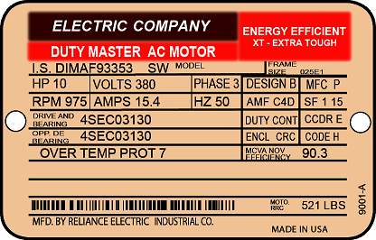
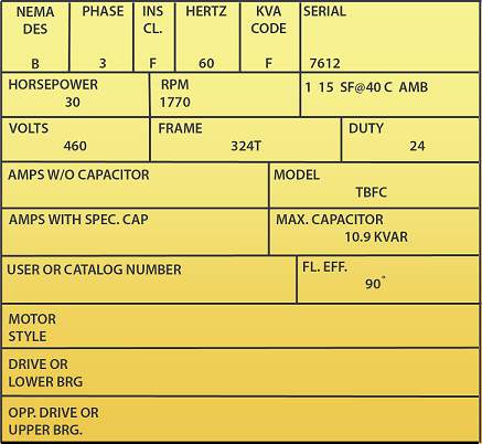
The National Electrical Code (NEC®) in Section 430.7 has specified information that must be on a motor nameplate based on its type (see Figure 1 and Figure 2). Requirements can also be found in NEMA® standards MG 1 and MG 2.
Rated Voltage
The rated or nameplate voltage is the voltage at which the motor operates most effectively. The nameplate rated voltage is usually lower than the system voltage. For example, in a 480-volt system, the motor nameplates associated with that system would likely indicate the rated voltage as being 460 volts. The manufacturers make an assumption that there will be a voltage drop of 20 volts from the transformer output to the motor input terminals. When the actual voltage differs from the nameplate, performance and motor life may be reduced. This is not necessarily true in all cases. It depends on the design of the motor and, specifically, whether the motor was designed as an energy efficient motor.
Nominal Rated Voltage
Nominal rated voltage is defined as "the voltage rating of the insulation to which the motor is designed to operate."
Minimum Starting Voltage
Minimum starting voltage may be defined as "the lowest voltage at which a motor will start without drawing an excessive/trip current."
Rated Amperage
Rated amperage may be defined as "the full load current that is required to produce full frequency."
Rated Speed
The rated speed of a motor is the speed at which the shaft will turn at synchronous motor.
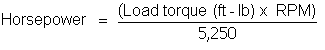
Rated Horsepower
An induction motor is really a torque generator. It delivers a needed torque to a driven machine at a certain speed. Thus:
For induction motors built to NEMA® standards, the ratings range from 1/2 to 400 hp – 24 in all. If horsepower requirements fall between any two ratings, the larger motor size should be selected.
Remember, an induction motor will try to deliver any amount of horsepower the load requires. If properly sized, most motors operate at something less than the motor nameplate horsepower. Standard motors are designed to operate at nameplate values from sea level up to an altitude of 3,300 feet if the ambient temperature does not exceed 104°F (40°C). Above this altitude, the nameplate horsepower no longer applies.
NEMA® standards provide a method for determining the proper temperature rise, or the new maximum ambient temperature, at higher elevations. However, the standards do not provide a direct method for deriving the horsepower. Several methods are available to estimate true motor horsepower output.
Rated Current
This is the full-load current of a motor that operates under rated frequency and voltage conditions at rated load (HP).
Full-load Amperes
Full-load amps (FLA) on the nameplate indicate the current the motor will draw at full rated load. This value should be valid if the motor is running at frequency. The full-load amps given on the nameplate is the information used to determine overload selection.
When the voltage or frequency is not what is indicated on the motor nameplate, the full-load current will change. It is possible to damage a motor when it is operated below its rated voltage or frequency, since motor current increases in both cases.
- At 110% of rated voltage, the motor shows a 7% decrease in FLA.
- At 90% of rated voltage, the motor shows an 11% increase in FLA.
- At 105% of rated frequency, the motor shows a 5-6% decrease in FLA.
- At 95% of rated frequency, the motor shows a 5-6% increase in FLA.
Voltage and frequency change the full-load amps drawn by the motor due to its inherently inductive characteristics.
Frame Sizes
Frame sizes were developed by NEMA® to ensure interchangeability of motors among manufacturers, and appear on motor nameplates to give information about the machine’s physical dimensions. Key dimensions are:
- Distance from motor feet to shaft centerline.
- Bolt hole center-to-center distance between front and back feet.
- Exposed shaft distance from shaft end to shaft shoulder.
Duty
This block on the nameplate defines the length of time during which the motor can carry its nameplate rating safely. Most often, this is continuous ("Cont"). Some applications have only intermittent use and do not need motor full-load continuously. Examples are crane, hoist, and valve actuator applications. The duty on such motors is usually expressed in minutes.
NEMA® Design Letter
The induction motor. Do not neglect this information when replacing motors, because ignoring the letter may lead to misapplication and overload coordination problems. Fans and centrifugal pumps have starting torque requirements that increase and vary with the square of the change in speed. However, mixers and conveyors have starting torque requirements that change little with changes in speed.
NEMA® letters A, B, C, D, and F account for difference in starting torque requirements among motors. In practicality, these differences are manifested in the design and construction of the rotor. Most industrial motors are NEMA® Design B motors because they drive conventional loads such as starting current drawn by a motor as being approximately six times the normal full-load current.
Table 2 shows an example of how starting current can vary significantly from the 6X value, and could conceivably cause unacceptable voltage drops or brown outs if the motor is large enough.
Table 2: Current Specifications for Various Motors
| Horsepower | Rated FLC | Classes B, C, and D Starting Current | Class F Starting Current |
|---|---|---|---|
| 0.5 | 2 | 12 | — |
| 1 | 3.5 | 24 | — |
| 1.5 | 5 | 35 | — |
| 2 | 6.5 | 45 | — |
| 3 | 9 | 60 | — |
| 5 | 15 | 90 | — |
| 7.5 | 22 | 120 | — |
| 10 | 27 | 150 | — |
| 15 | 40 | 220 | — |
| 20 | 52 | 290 | — |
| 25 | 64 | 365 | — |
| 30 | 78 | 435 | 270 |
| 40 | 104 | 580 | 360 |
| 50 | 125 | 725 | 450 |
| 60 | 150 | 870 | 540 |
| 75 | 185 | 1085 | 675 |
| 100 | 246 | 1450 | 900 |
| 125 | 310 | 1815 | 1125 |
| 150 | 360 | 2170 | 1350 |
| 200 | 480 | 2900 | 1800 |
Insulation Class
Often abbreviated "INSUL CLASS" on nameplates, it is an industry standard classification of the thermal tolerance of the motor winding. Insulation class is a letter designation such as A, B, or F, depending on the winding’s ability to survive a given operating temperature for a given life. Insulations of a letter higher into the alphabet perform better. For example, class F insulation has a longer nominal life at a given operating temperature than class A, or for a given life, it can survive higher temperatures.
Operating temperature is a result of ambient conditions plus the energy lost in the form of heat (causing the temperature rise) as the motor converts electrical to mechanical energy.
Service Factor
Service factor is a measure of the extra horsepower a motor can deliver if it is operating under rated conditions and is located in an acceptable ambient environment. A common service factor is 1.15. This means that a motor could deliver 115% of the horsepower indicated on the nameplate.
KVA Code Letter
When a motor is started, it draws higher current than it delivers under full-load. This locked-rotor current. While most electricians estimate inrush current as being six times full-load current, this is not always the case. The amount of current drawn by a particular motor is determined from the KVA code letter on the motor nameplate. Table 3 shows KVA code letters and the corresponding KVA required per horsepower.
Table 3: KVA Code Letters
| KVA Code Letter | KVA per HP with Locked Rotor |
| A | 0 – 3.14 |
| B | 3.15 – 3.54 |
| C | 3.55 – 3.99 |
| D | 4.0 – 4.49 |
| E | 4.5 – 4.99 |
| F | 5.0 – 5.59 |
| G | 5.6 – 6.29 |
| H | 6.3 – 7.09 |
| J | 7.1 – 7.99 |
| K | 8.0 – 8.99 |
| L | 9.0 – 9.99 |
| M | 10.0 – 11.19 |
| N | 11.2 – 12.49 |
| P | 12.5 – 13.99 |
| R | 14.0 – 15.99 |
| S | 16.0 – 17.99 |
| T | 18.0 – 19.99 |
| U | 20.0 – 22.39 |
| V | 22.4 – higher |
This letter may become important when a 20 HP motor must be replaced. If the motor being replaced had a KVA code letter of D, and was being replaced by a 20 HP motor found in a storage area with a KVA code letter of R, the replacement motor would pull much higher starting current than the motor being replaced. This situation may cause electricians to think the replacement motor has bearing problems or other problems that would cause such a high inrush current. Overloads may trip, and anxieties and confusion may result.
Power Factor
A motor’s power factor is the ratio of kilowatt input to the kilovolt-ampere input. The number is expressed as a percentage. The electric motor manufacturers compute the power factor of a number of motors that are loaded at a rated load and a rated voltage. The power factors of all these motors are then averaged.
Temperature Rise
This is the heat produced by the motor itself. It is the temperature rise above the ambient temperature in which the motor is physically located. For example, a motor rated at 40°C rise operating in a 20°C environment should not indicate over 60°C when a direct contact temperature indicating device, or thermal probe, is used. As an electrician, you may use thermal devices to determine motor temperatures and you should know the conditions under which a motor develops temperature in excess of its temperature rise. You should know that the majority of motor losses are caused by a breakdown of the insulation system, whether rapid or progressive. Heat-related breakdowns are common, and must be monitored and corrected by the actions of inspectors. There will be more information on temperature rise and the variables that affect it later in this article.
Frequency
Frequency is given for AC motors in hertz. Standard frequencies for AC motors are 50 and 60 Hz (cycles per second). Alternating current in the US has a standard frequency of 60 Hertz per second.
Bearings
Polyphase induction motors require either anti-friction or sleeve bearings. Anti-friction bearings are standard in medium (integral) horsepower motor sizes through 125 hp/1800 RPM. They are optional in 150 to 600 hp/1800 RPM sizes. Sleeve bearings are standard in 500 hp/3600 RPM and larger sizes.
Since radial loads are higher at the drive end of the motor, the drive-end bearing has a higher load rating than the bearing at the opposite end. A typical nameplate might depict both bearing duties as:
- Drive shaft brg: 6309 (medium duty)
- Opp dr shaft brg: 6207 (light duty)
Bearing internal clearances are C1, C2 (smaller than normal clearance), standard clearance (normal), C3, C4, and C5 (larger than normal clearance). Electric motors usually require a C3 internal clearance. Some bearing manufacturers have a different designation for motor bearings that have a larger-than-normal internal clearance.
Locked-Rotor Current
Locked-rotor current is the steady state current of a motor with the rotor locked and with squirrel cage induction motors. KVA (thousands of volts multiplied by amperes) is an indication of the current drawn and, indirectly, the impedance of the locked-rotor.
Table 4: NEMA® Table 430-7(b): Locked-Rotor Indicating Code Letters
| Code Letter | Kilovolt-Amperes Per Horsepower With Locked-Rotor |
| A | 0 – 3.14 |
| B | 3.15 – 3.54 |
| C | 3.55 – 3.99 |
| D | 4.0 – 4.49 |
| E | 4.5 – 4.99 |
| F | 5.0 – 5.59 |
| G | 5.6 – 6.29 |
| H | 6.3 – 7.09 |
| J | 7.1 – 7.99 |
| K | 8.0 – 8.99 |
| L | 9.0 – 9.99 |
| M | 10.0 – 11.19 |
| N | 11.2 – 12.49 |
| P | 12.5 – 13.99 |
| R | 14.0 – 15.99 |
| S | 16.0 – 17.99 |
| T | 18.0 – 19.99 |
| U | 20.0 – 22.39 |
| V | 22.4 and up |
These nameplate code ratings give a good indication of the starting current the motor will draw if the motor cannot turn. These code letters are sequenced so that a letter at the beginning of the alphabet indicates a relatively low locked-rotor current, and a letter at the end of the alphabet indicates a high current per horsepower rating of the motor.
Computation of the starting current can be accomplished using the formula:
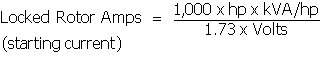
Example: What is the approximate starting current of a 7 % hp, 220-volt motor with a nameplate code letter of G?
Solution: The kVA/hp for a code letter of G is 5.6 to 6.3. Taking a number approximately halfway in between and substituting in the formula, we get:
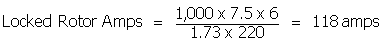
Therefore, the locked-rotor current is approximately 118 amperes. This locked-rotor current characteristic is important when purchasing a motor because the buyer must know what current-carrying capacity and overload protection to provide. The buyer must install branch circuit lines large enough to carry the required currents and put in fuses or circuit breakers of the proper size.
Motor Protection
This section deals with the protection of attended induction motors, synchronous condensers, and the motors of frequency converters. Motors in unattended stations must be protected against all harmful abnormal conditions. The protection of very small motors is not specifically described, although the same basic principles apply; this subject is treated in detail in the National Electrical Code®. The practices described here for large motors are at least equal to those covered by the Code, and are generally more comprehensive. However, it is recommended that the Code be consulted whenever it applies.
The starting energy requirements of AC motors are spread over seconds rather than milliseconds, and vary considerably with the type of load and with the inertia of the load. However, the peak amplitude of the starting current is generally within reasonable values.
The table below provides some typical figures as observed on motors selected at random. Note that single-phase induction motors are the worst, usually having a starting winding that can draw 7 or 8 times the running current for the better part of a second. A 750-millisecond surge duration was observed on several of the various horsepower ratings.
| MOTOR START | |||||
| (1)Motor Type | (2)Start CurrentPeak Ampl. RMS | (3)Duration of Start Surge in Sec. | (4)Load Second% 1 t Sec. | (5)APL Delay 62 | (6)APL Delay 66 |
| Shaded Pole | 150% | 2.0 | 0.3 | OK | OK |
| Series AC-DC | 530% | 0.100 | 0.5 | NO | OK |
| Series AC-DC | 200% | 0.400 | 0.8 | OK | OK |
| Series AC-DC | 333% | 0.167 | 0.5 | OK | OK |
| Split Phase | 600% | 0.116 | 0.7 | NO | OK |
| Split Phase | 425% | 0.500 | 2.0 | NO | OK |
| Capacitor Load | 400% | 0.600 | 2.4 | NO | OK |
| Capacitor No-load | 300% | 0.100 | 0.3 | OK | OK |
| Capacitor Load | 420% | 0.500 | 2.1 | NO | OK |
| Induction | 700% | 0.750 | 5.0 | NO | NO |
| 3 Phase | 350% | 0.167 | 0.6 | OK | OK |
| Cap. Start. Split Phase Run | 290% | 0.083 | 0.24 | OK | OK |
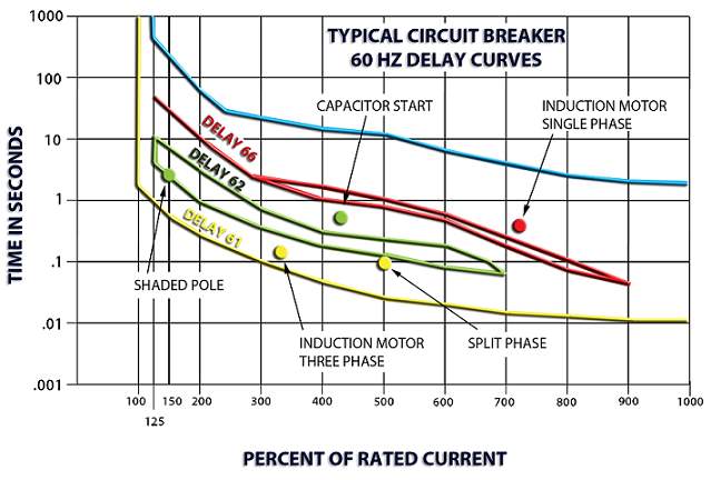
Most magnetic breakers exhibit a reasonably flat frequency response – trip point versus frequency – in applications between 20 and 200Hz. For any response beyond 200Hz, up to 440Hz, special design considerations are required. Beyond 440Hz, the breaker supplier must be consulted.
A thermal device imbedded inside the motor usually protects induction motors. Most protectors that will handle the starting surge will not trip out soon enough on lesser overloads to prevent damage to the motor. Here, you are protecting the power wiring rather than the device. Magnetic protectors are available which offer a better compromise. Figure 3 shows three delays for several different motors. The marginal position of single-phase induction motors is obvious.
Short-Circuit Protection of Stator Windings
Overcurrent protection is the basic type that is used for short-circuit protection of stator windings. The equipment for this type of protection ranges, from fuses for motor voltages of 600-volts and lower, through direct-acting overcurrent tripping elements on circuit breakers, to separate overcurrent relays and circuit breakers for voltages of 2200-volts and higher.
Protection should be provided against a fault in any ungrounded conductor between the interrupting device and the motor, including its stator windings. Where fuses or direct-acting tripping devices are used, there must be one protective element in each ungrounded conductor. Where relays and current ground relay will suffice for a three-phase circuit whether or not the source neutral is grounded.
Motors Other than Essential-Service
For all except "essential-service" motors, it is the practice to provide both inverse-time and instantaneous phase and ground faults within about 10% of the winding from the neutral end.
Percentage-differential relaying is provided for large motors. It is the practice of manufacturers to recommend such protection for motors of the following ratings:
- 2200- to 4999-volts, inclusive, 1500 hp and higher;
- 5000-volts and higher, 501 hp and higher
The advantage of percentage-differential relaying is that it will provide faster and more sensitive protection than overcurrent relaying, but at the same time, it will not operate on starting or other transient overcurrents.
Essential-Service Motors
For essential-service motors, the inverse-time phase overcurrent relays are usually omitted, leaving the instantaneous phase relays and the inverse-time and instantaneous stator overheating protection, supplementary protection against phase overcurrents less than locked-rotor values is provided.
Stator-Overheating Protection
All motors need protection against overheating resulting from an overload, a stalled rotor, or unbalanced stator currents. For complete protection, three-phase motors should have an overload element in each phase; this is because an open circuit in the supply to the power transformer feeding a motor will cause twice as much current to flow in one phase of the motor as in either of the other two phases, as shown in Figure 4. Consequently, to be sure that there will be an overload element in the most heavily loaded phase no matter which power-transformer phase is open-circuited, one should provide overload elements in all three phases. In spite of the desirability of overload elements in all three phases, motors rated about 1500 hp and below are generally provided with elements in only two phases on the assumption that the open-phase condition will be detected and corrected before any motor can overheat.
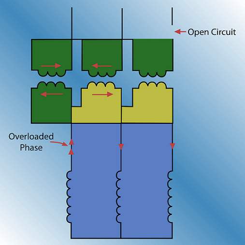
Single-phase motors require an overload element in only one of the two conductors.
Motors Other than Essential Service
Except for some essential-service motors, whose protection will be discussed later, it is the practice for motors rated less than about 1500 hp to provide either replica-type thermal-overload relays or long-time inverse-time overcurrent relays or direct-acting tripping devices to disconnect a motor from its source of supply in the event of overload. Which type of relay to use is largely a matter of personal preference.
Other things being equal, the replica type will generally provide the best protection because, as shown in Figure 5, its time-current characteristic more nearly matches the heating characteristic of a motor over the full range of overcurrent. In addition, it may take into account the heating effect of the load on the motor before the overload condition occurred.
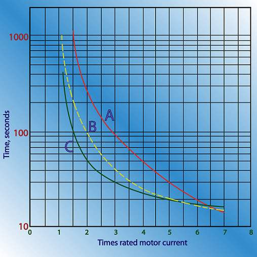
The inverse-time overcurrent relay will tend to "overprotect" at low currents and to "under protect" at high currents, as shown in Figure 5. However, the overcurrent relay is very easy to adjust and test, and it is self-reset.
- For continuous-rated motors without service factor or short-time overload ratings, the protective relays or devices should be adjusted to trip at not more than about 115% of rated motor current.
- For motors with 115% service factors, tripping should occur at not more than about 125% of rated motor current.
- For motors with special short-time overload ratings, or with other service factors, the motor characteristic will determine the required tripping characteristic, but the tripping current should not exceed about 140% of rated motor current.
Obtain the manufacturer’s recommendations in each case.
The overload relays will also provide protection in the event of phase-to-phase short circuits, and in practice, one set of such relays serves both purposes wherever possible.
A survey of the practice of a number of power companies (45) showed that a single set of long-time inverse-time overcurrent relays, adjusted to pick up at 125 to 150% of rated motor current, is used for combined short-circuit and overload protection of non-essential auxiliary motors; they are supplemented by instantaneous overcurrent relays adjusted as already described. Such inverse-time overload relays must withstand short-circuit currents without damage for as long as it takes to trip the breaker. In addition, the minimum requirements as to the number of relays or devices for either function must be fulfilled.
Motors rated higher than about 1500 hp are generally provided with resistance temperature detectors embedded in the stator slots between the windings. If such temperature detectors are provided, a single relay operating from these detectors is used instead of the replica-type or inverse-time overcurrent relays. In addition, current-balance relays capable of operating on about 25% or less unbalance between the phase currents should be supplied. If the motor does not have resistance temperature detectors, but is provided with current-balance relays, a single replica-type thermal overload relay may be substituted for the resistance-temperature-detector relay.
Specially cooled or ventilated motors may require other types of protective equipment than those recommended here. For such motors, the manufacturer
Essential-Service Motors
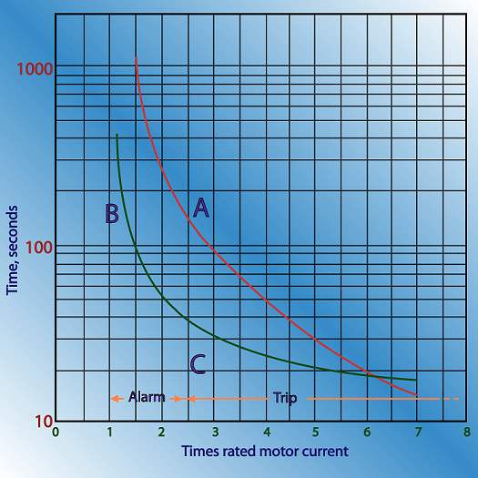
The protection recommended for some essential-service motors is based on minimizing the possibility of unnecessarily tripping the motor, even though such practice may sometimes endanger the motor. In other words, long-time inverse-time overcurrent-relays are provided for all motor ratings, but they merely control an alarm and leave tripping in the control of an operator. Then, for motors that can suffer locked rotor, supplementary instantaneous overcurrent relays adjusted to pick up at about 200 to 300% of rated motor current are used, and their contacts are connected in series with the contacts of the inverse-time-overcurrent relays to trip the motor breaker automatically. The instantaneous relays should be of the high-reset type to be sure that they reset when the current returns to normal after the starting inrush has subsided. The protection provided by this type of equipment is shown in Figure 6.
For essential-service motors for which automatic tripping is desired in addition to the alarm for overloads between about 115% of rated current and the pickup of the instantaneous overcurrent relays, thermal relays of either the replica type or the resistance-temperature detector type should be used, depending on the size of the motor. Such relays permit operation for overloads as far as possible beyond the point where the alarm will be sounded, but without damaging the motor to the extent that it must be repaired before it can be used again.
Rotor-Overheating Protection
Squirrel-Cage Induction Motors
The replica-type or the inverse-time overcurrent relays, recommended for protection against stator overheating, will generally protect the rotor except where high-inertia load is involved; such applications should be referred to the manufacturer for recommendations. Where resistance-temperature detector relaying is used, a single replica-type or inverse-time overcurrent relay should be added for rotor protection during starting.
Wound-Rotor Induction Motors
General recommendations for this type of motor cannot be given except that the stator-overheating protective equipment that has been described may not protect the rotor. Each application should be referred to the manufacturer for recommendations.
Synchronous Motors
Amortisseur-overheating protection during starting or loss of synchronism should be provided for all "loaded-start" motors. (A loaded-start motor is a motor other than a synchronous condenser or a motor driving a generator; it includes any motor driving a mechanical load even though automatic unloading means may be employed.) Such protection is best provided by a time-delay thermal overload relay connected in the field-discharge circuit.
Amortisseur-overheating protection is not required for "unloaded-start" motors (synchronous condensers or motors driving generators). An unloaded-start motor is not likely to fail to start on the application of normal starting voltage. In addition, loss-of-synchronism protection that is provided either directly or indirectly will provide the necessary protection. An exception to this is a condenser or a motor that has an oil-lift pump for starting.
Where voltage regulators without automatic field current-limiting features. A thermal overload relay with time delay or a relay that responds to an increase in the field-winding resistance with increasing temperature may be used. In an attended station, the relay would merely control an alarm.
Loss-of-Synchronism Protection
All loaded-start synchronous motors should have protection against loss of synchronism generally arranged to remove the load and the excitation temporarily and to reapply them when permissible. Otherwise, the motor is disconnected from its source.
For unloaded-start motors, except the synchronous motor of a frequency converter, the combination of loss-of-excitation protection, and the DC generator overcurrent protection that is generally furnished will provide satisfactory loss-of-synchronism protection. Should additional protection be required, it can be provided by an inverse-time overcurrent relay energized by the current in the running connection and arranged to trip the main breaker. Usually, automatic resynchronizing is not required. All frequency converters interconnecting two systems should have loss-of-synchronism protection on the synchronous machine side. With synchronous-synchronous sets, protection may be required on both sides. The protective relaying equipment should be arranged to trip the main breaker on its side.
Undervoltage Protection
All AC motors, except essential-service motors, should have protection against undervoltage on at least one phase during both starting and running. For polyphase motors larger than about 1,500 hp, polyphase undervoltage protection is generally provided. Wherever possible, the protective equipment should have inverse-time delay characteristics.
"Undervoltage release", which provides only temporary shutdown on voltage failure and which permits automatic restart when voltage is re-established, should not be used with such equipment as machine tools, etc., where automatic restart might be hazardous to personnel or detrimental to process or equipment.
Loss-of-Excitation Protection
All unloaded-start voltage regulators, should have loss-of-excitation protection in the form of a low-set, time-delay-reset undercurrent relay whose coil is in series with the field winding.
If a motor has stator-overheating protection, this equipment indirectly provides loss-of-excitation protection.
Branch Considerations
When a single motor is supplied from a branch circuit, the ampacity of the branch circuit must be ≤125 percent of motor full-load current. Overcurrent protection must include up to a 20-second time delay for induction motors. If a multi-speed motor is used, the ampacity shall be based on the largest sized motor. Where motors have unusual duty cycle requirements, use the requirements as listed in Table 5.
Table 5: NEC® Table 430.22(E) Duty Cycle Service
| PercentageofNameplate Current Rating | ||||
| ClassificationofService | 5 MinuteRatedMotor | 15 MinuteRatedMotor | 30 & 60Min. RatedMotor | ContinuousRatedMotor |
| Short Time DutyOperating valves, raising or lowering rolls, etc. | 110 | 120 | 150 | — |
| Intermittent DutyFreight and passenger elevators, tool heads, pumps, drawbridges, turntables, etc. For arc welders, see Section 630 21 | 95 | 85 | 90 | 140 |
| Periodic DutyRolls, ore and coal handling machines, etc. | 85 | 90 | 95 | 140 |
| Varying Duty | 110 | 120 | 150 | 200 |
Note: Any motor application shall be considered as continuous duty unless the nature of the apparatus it drives is such that the motor will not operate continuously with load under any condition of use.
If there are several motors on one circuit, the ampacity shall be equivalent to the sum of the individual motor ampacity plus 25 percent of the full-load current rating of the largest motor. Several motors or loads are permitted to be provided for on one branch circuit if:
-
System voltage is
< 600 volts. - The branch protective device protects the smallest installed motor.
- All motors are ≤ 1HP, ≤ 20A (15A) on 120V (600V) circuits where each motor draws ≤6A, overloads are installed on the motor, and short circuit current and ground fault current do not exceed the branch circuit rating.
- It is part of a factory-listed assembly.
In instances where taps are used, short circuit current and ground fault current protection may not be required for the taps used. This is true if the tap used has the same ampacity as the branch circuit it is connected to. Additionally, the tap cannot be longer than 25 feet and it must be physically protected from damage.
Thermal Protectors
Thermal protectors are used to protect the motor from overloads and starting failures. All motors with a voltage rating greater than 600V must have a thermal protector, and their overload must not have an automatic reset feature. They shall be set as follows:
- Motor full-load current not exceeding 9 amperes 170 percent
- Motor full-load current 9.1 to and including 20 amperes 156 percent
- Motor full-load current greater than 20 amperes 140 percent
- This requirement is based on the maximum full-load motor current as listed in tables provided in Section 430 of the NEC®.
- Motors that are rated ≤ 1500 HP include an RTD in their design which is set to de-energize the motor once the actual temperature rise of the motor equals the rated temperature rise of the motor’s insulation.
Alternating Current Motors
Alternating current (AC) motors can be divided into two major types: single-phase and polyphase motors. A single-phase motor is normally limited to fractional horsepower ratings up to five horsepower. They are commonly used to power such things as fans, small pumps, appliances, and other devices not requiring a great amount of power. Single-phase motors are not likely to be connected to complicated motor control circuitry, and will not be discussed in this text.
Polyphase motors comprise the majority of motors needed to drive large machinery such as pumps, large fans, and compressors found in industrial facilities. These motors have several advantages over single-phase motors in that they do not require a separate winding or other device to start the motor; they have relatively high starting torque and good speed regulation for most applications.
There are two classes of polyphase motors: induction and synchronous. The rotor of a induction motor revolves at a speed somewhat less than synchronous speed. The differences in rotor speed are due to differences in construction and operation. Both are discussed in depth after a review of motor theory.
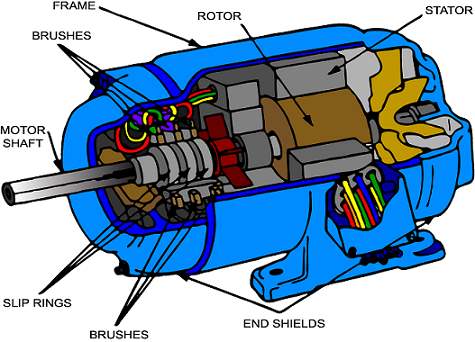
AC Motor Theory
AC motors consist of two parts: the stator, or stationary part, and the rotor, or revolving part. The stator is connected to the incoming three-phase AC power. The rotor in an synchronous motors is connected to external power. Both induction and synchronous motors operate on the principle of a rotating magnetic field.
Rotating Fields
This section shows how the stator windings can be connected to a three-phase AC input to create a magnetic field that rotates. Another magnetic field in the rotor can be made to chase it by being attracted and repelled by the stator field. Because the rotor is free to turn, it follows the rotating magnetic field in the stator.
Polyphase AC is brought into the stator and connected to windings that are physically displaced 120 degrees apart. These windings are connected to form north and south magnetic poles, as shown in Figure 7. An analysis of the electromagnetic polarity of the poles at points 1 through 7 in Figure 7 shows how the three phase AC creates magnetic fields that rotate.
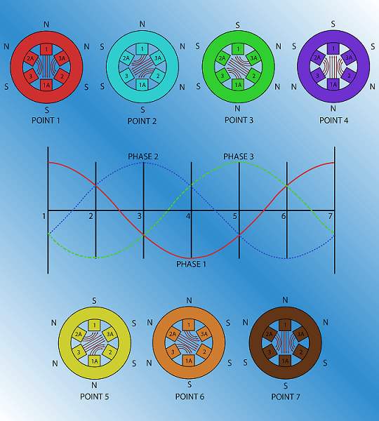
At point 1, the magnetic field in phase 1 is at maximum. Negative voltages are shown in phases 2 and 3. The negative voltages in these windings create smaller magnetic fields, which will tend to aid the field set-up in coil 1-1A.
At point 2, phase 3 creates a maximum negative flux in coil 3-3A. This strong negative field is aided by the weaker magnetic fields developed by phases 1 and 2.
The three-phase AC input rises and falls with each cycle. Analyzing each point on the voltage graph shows that the resultant magnetic field rotates clockwise. When the three-phase input completes a full cycle at point 7, the magnetic field has completed an entire revolution of 360 degrees.
Rotor Behavior in a Rotating Field
An oversimplification of rotor behavior shows how the magnetic field of the stator influences the rotor. First, assume that a simple bar magnet were placed in the center of the stator diagrams shown in Figure 7. Also, assume that the bar magnet is free to rotate. It has been aligned so that at point 1, its south pole is opposite the large North of the stator field.
Unlike poles attract and like poles repel. As the AC completes a cycle, going from point 1 to point 7, the stator field rotates and pulls the bar magnet with it because of the attraction of unlike poles and the repulsion of like poles. The bar magnet would be rotating at the same speed of the revolving flux of the stator. This speed is known as synchronous speed. Synchronous speed of a motor is given by the equation:
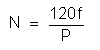
| Where: | N = speed in RPM f = frequency in cycles per second P = number of magnetic poles |
Induction
Current flowing through a conductor sets up a magnetic field around the length of the conductor. Conversely, a conductor in a magnetic field will produce a current when the magnetic lines of flux cut across the conductor. This action is called induction because there is no physical connection between the magnetic field and the conductor. Current is induced in the conductor.
In motors, the rotating magnetic field of the stator induces a magnetic field in the rotor. This is simply because it first induces a voltage in the rotor, and since the rotor is made up of conductors, a current is induced. The induced current in the rotor sets up its own magnetic field.
The voltage induced by the action of the rotating magnetic field of the stator cutting across the rotor bars is also known as electromotive force or EMF. In order for an EMF to be induced, three conditions must be present:
- A magnetic field
- A current-carrying conductor
- Relative motion between the two
This does not mean that the conductor must be carrying current. It simply means that the conductor must consist of a closed path capable of carrying current.
An equation for EMF is:
EMF = βVL
| Where: | β | = magnetic flux density in Webers per square meters |
| V | = conductor or field velocity in meters per second | |
| L | = length of the conductor in meters |
This EMF, or induced voltage, and the resultant current flow sets up its own magnetic field. The interaction of the magnetic field of the stator and the magnetic field of the rotor causes motor induction motor is discussed in detail later in this article.
Induction Motors
Three-phase rotor that is not connected to any external sources of power. It derives its name from the fact that the AC voltages are induced in the rotor due to the rotating magnetic field of the stator.
Construction
Three-phase induction motor.
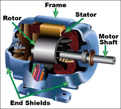
Stator
The stator contains a three-phase winding mounted in the slots of a laminated steel core. The winding consists of formed coils of wire that are spaced so that they are 120 electrical degrees apart. These three windings can be connected wye or delta. To facilitate this, nine leads are usually brought out of the motor into the motor terminal box. Many motors have two windings per phase, which allows the motor to be connected to either low-voltage (phase windings in parallel) or high-voltage (phase windings in series).
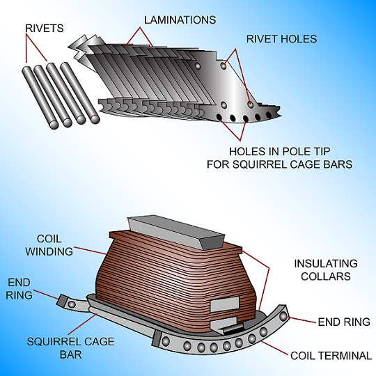
Rotor
An induction rotor is composed of a laminated cylinder with slots in its surface. The windings in these slots are one of two types, as shown in Figure 9. The most common is the squirrel cage rotor. This entire winding is composed of heavy copper bars imbedded near the outer surface of the rotor. These copper bars are brazed or welded to two copper (or brass) end rings at the end of the rotor drum. No insulation is required between the core and the rotor bars because of the very low voltages generated in the rotor bars. The copper bars and the end rings resemble a squirrel cage, thus the name.
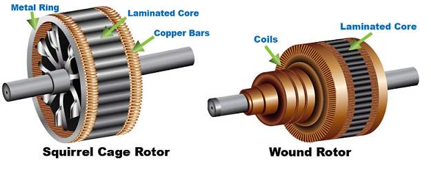
The rotor may also have fan blades to circulate cooling air through the motor frame, and the shaft of the rotor contains the necessary keyway or splines to connect pulleys, gears, or other devices to transmit the motor torque to its load.
Regardless of which type of rotor is used, the principle of operation is essentially the same. The AC applied to the stator creates a revolving magnetic field, which induces an EMF and current in the copper bars of the rotor. This, in turn, creates its own magnetic field. These two fields then interact to produce rotation and torque. The air gap between the rotor and stator is small, in order to produce a maximum interaction between these two fields.
Lenz
It is impossible for the rotor in an induction motor to rotate at synchronous speed (the speed of the revolving field of the stator). If the speeds were the same, there would be no relative motion between the two and an EMF would not be developed. This is because the rotating magnetic field of the stator must cut the rotor bars to cause an EMF and create the rotor field.
In order for relative motion to remain between the two, the rotor will always revolve at a speed slightly less than synchronous speed. The difference between the speed of the rotor and the synchronous speed is called slip.
If a three phase induction motor’s rotor speed is subtracted from the motor
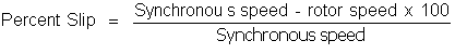
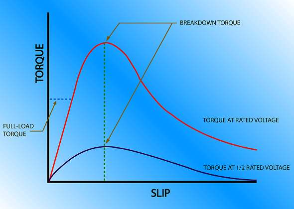
The range of percent slip for induction motors is between 2 and 6 percent. As load is applied to a motor, slip increases almost linearly up to the breakdown torque of the motor, at which time the slip increases non-linearly with increases in torque beyond that point. If the motor is loaded beyond this point, there will be a corresponding decrease in torque until the point is reached where the motor stalls.
Torque
As previously stated, torque in an induction motor is caused by the interaction of the rotor and stator fields. In order that an EMF and corresponding currents are induced in the rotor, it rotates at a slip. At no-load, the rotor will lag behind the stator flux by a small amount necessary to produce the minimum torque required to overcome the rotor weight and motor losses. As load is added, the rotor speed will naturally increase. This decrease in speed (increase in slip) allows the stator field to rotate past the rotor bars at a faster rate, inducing larger rotor currents and a larger rotor field. The result is a larger torque at a slower speed.
Since the rotor impedance is low, a small decrease in rotor speed results in a large increase in rotor current and a large increase in the strength of the rotor field. As the load increases, the larger rotor currents are in such a direction as to decrease the stator flux. This results in a temporary decrease in counter EMF in the stator windings. This, in turn, allows more current to flow into the stator and increases the power input to the motor.
The strength of the rotor and stator fields, as well as the phase relationships between them, governs torque.
Torque = KβI pf
| Where: | K | = a constant |
| β | = rotating strator flux intensity | |
| l | = rotor current | |
| pf | = rotor power factor |
The power factor of the rotor is dependent on the phase relationship, since power factor is the cosine of the phase angle.
During normal operations, K, β, and pf are nearly constant. The torque will increase directly with the rotor current. The rotor current increases almost directly with slip. Increases in slip cause an increase in rotor frequency and rotor reactance.
To understand this, consider a two-pole induction motor. Synchronous speed is calculated at 3,600 rpm. If this motor operates at a 5 percent slip, then the slip in rpm is:
3,600 x .05 = 180 rpm
Physically, this means that a pair of stator poles will pass a certain rotor conductor 180 times a minute, or three times a second. Each time a pair of poles moves across a certain conductor, one cycle of EMF will be induced, resulting in a frequency of three cycles per second. If the slip were to increase to ten percent, or 360 rpm, the frequency of the rotor voltage and current is increased to six cycles per second. If the slip were to increase to 100 percent, the rotor frequency would be 60 Hz.
From this, you can see how rotor frequency is dependent on slip.
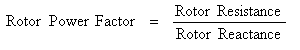
Rotor Frequency = Stator Frequency x Slip
From this, we see how increases in slip cause an increase in rotor frequency and rotor reactance. The rotor resistance will be constant, so an increase in rotor reactance means a decrease in rotor power factor since: [[Image:Rotor Power Eq.PNG|frameless|800px|center|]]
During normal operations, the change in slip is very small as load is added from an unloaded to a fully loaded condition. This means that changes in rotor impedance and reactance are tactically negligible. However, as the load is increased beyond rated and full-load values, the slip increases appreciably. This increase will lower the rate that rotor current increases in such a manner as to result in a torque that does not increase directly with slip.
The decreasing power factor and the lowered rate of current increase will result in torque increases that become less rapid and will finally reach a maximum value. This is usually about 20 percent slip in squirrel cage induction motors. This maximum value of torque is known as pullout torque. If the load increases even further, the rotor power factor will decrease faster than the rotor current increases, resulting in a decreasing torque and stalling the motor. Figure 10 shows the relationship between torque and slip.
Starting Current
At the moment a three-phase induction motor is started, the current supplied to the motor stator terminals may be as high as six times the motor full-load current. This is because at starting, the rotor is at rest; therefore, the rotating magnetic field of the stator cuts the squirrel cage rotor at the maximum rate, inducing large amounts of EMF in the rotor. This results in proportionally high currents at the input terminals of the motor, as previously discussed. Because of this high inrush, current starting protection as high as 300 percent of full-load current must be provided to allow the motor to start and come up to speed.
Since there exists 100 percent slip at the instant the motor is energized, the rotor current lags the rotor EMF by a large angle. This means that the maximum current flow occurs in a rotor conductor at a time after the maximum amount of stator flux has passed by. This results in a high starting current at a low power factor, which results in a low value of starting torque.
As the rotor speeds up, the rotor frequency and rotor reactance decrease, causing the torque to increase up to its maximum value, then decrease to the value needed to carry its load.
Power Factor
The power factor of a squirrel cage induction motor is poor at no-load and low load conditions. At no-load, the power factor can be as low as 15 percent lagging. However, as load is increased, the power factor increases. At high rated load, the power factor may be as high as 85 to 90 percent lagging.
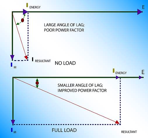
The power factor at no-load is low because the magnetizing component of input current is a large part of the total input current of the motor. When the load on the motor is increased, the in-phase current supplied to the motor increases, but the magnetizing component of current remains practically the same. This means that the resultant line current is more nearly in-phase with the voltage and the power factor is improved when the motor is loaded, compared with an unloaded motor, which mainly draws magnetizing current.
Figure 11 shows the increase in power factor from a no-load condition to full-load. In the no-load diagram, the in-phase current (IENERGY) is small when compared to the magnetizing current (IM); thus, the power factor is poor at no-load. In the full-load diagram, the in-phase current has increased while the magnetizing current remains the same. As a result, the angle of lag of the line current decreases and the power factor increases.
Speed Control
The speed of a three-phase squirrel cage induction motor depends on the synchronous speed of the applied voltage and the number of poles in the motor, therefore this type of motor has virtually no speed control. As a result, these motors are used in applications where speed remains constant and where it can be controlled by other means such as variable speed drives.
Reversing Rotation
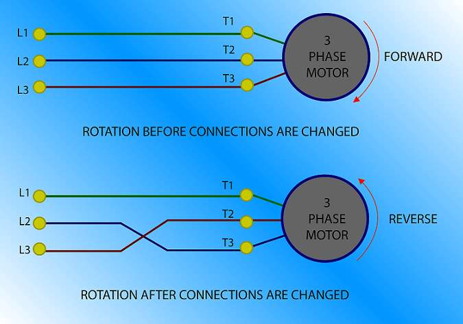
The direction of rotation of a three-phase induction motor can be readily reversed. The motor will rotate in the opposite direction if any two of the three incoming leads are reversed, as shown in Figure 12.
Synchronous Motors
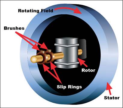
The synchronous motor is a three-phase motor that operates at synchronous speed from no-load to full-load.
This type of motor has a revolving field that is energized from a separate source than the stator winding. The rotor is excited by a direct current source. The magnetic field set up by the direct current on the rotor then locks in with the rotating magnetic field of the stator and causes the rotor to revolve at synchronous speed. By changing the magnitude of DC excitation, the power factor of the motor can be changed and can, in fact, be changed over a wide variety of power factors from leading to lagging. Because of the unique ability to change power factors, synchronous motors are often used as power factor correctors. They are most often used in applications that require precise speed regulation from no-load to full-load.
Construction
The construction of synchronous motors is essentially the same as the construction of three-phase generators. It has three stator windings that are 120 electrical degrees apart and a wound rotor that is connected to slip rings where the rotor excitation current is applied.
When three-phase AC is applied to the stator, a revolving magnetic field is created just as it is in induction motors. The rotor is energized with DC, which creates a magnetic field around the rotor. The strong rotating magnetic field of the stator attracts the rotor field. This results in a strong turning force on the rotor shaft.
This is how the synchronous motor works once it is started. However, one of the disadvantages of this type of motor is that applying only DC to the stator cannot start it. When AC is applied to the stator, the high-speed rotating magnetic field rushes past the rotor poles so quickly that the rotor does not have a chance to get started. The rotor is locked; it is repelled in one direction and then in another direction. In its purest form, the synchronous motor has no starting torque.
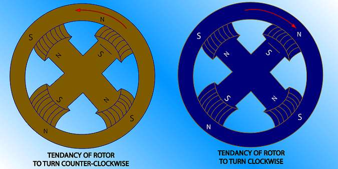
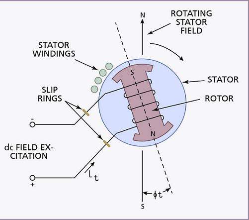
This is easier to understand using Figure 13. When the stator and rotor fields are energized, the poles of the rotating field approach the poles of the rotor poles of opposite polarity. The attracting force will tend to turn the rotor in a direction opposite that of the rotating field. As the rotor starts to move in that direction, the rotating field moves past the rotor poles and tends to pull the rotor in the same direction as the rotating field. The result is no starting torque.
To allow this type of motor to start, a squirrel cage winding is added to the rotor to cause it to start like an induction motor. This winding is called an amortisseur winding. The rotor windings are constructed such that definite north and south poles are created so that these poles, when excited by DC, will lock in with the revolving field. The rotor windings are wound about the salient field poles, which are connected in series for opposite polarity. The number of field poles must equal the number of stator poles. The rotor field windings are brought out to slip rings that are mounted on the rotor shaft. The field current is supplied through carbon brushes to the field windings.
Figure 14 shows a simplification of a synchronous motor. Figure 15 shows the construction of the rotor pole assembly.
Synchronous Motor Operating Principles
When a synchronous motor is started, current is first applied to the stator windings. Current is induced in the amortisseur winding and the motor starts as an induction motor. The motor then comes up to near synchronous speed to about 5-10 percent slip. At that point, the field is excited and the motor, turning at high speed, pulls into synchronism. When this occurs, the rotor is turning at synchronous speed and the squirrel cage winding will not be generating any current and, therefore, not affecting the synchronous motor
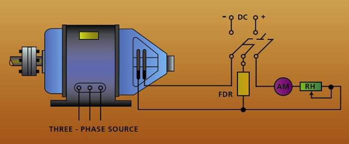
Rotor Field Excitation
The rotor must be excited from an external DC source. Figure 16 shows a simplified synchronous motor excitation circuit. Notice that the rheostat can vary the DC field current. However this does not change the speed of the motor. It only changes the power factor of the motor stator circuit. If full resistance is applied to the rotor field circuit, then the field strength of the rotor is at minimum and the power factor is extremely lagging. As the DC field strength is increased, the power factor improves and, if current is increased sufficiently, the power factor can be increased to near unity or 100 percent. This value of field current is referred to as normal excitation. By increasing the rotor field strength further, the power factor decreases but in a leading direction; that is, the stator circuit becomes capacitive and the motor is said to be overexcited. The synchronous motor can be used to counteract the lagging power factor in circuits by adding capacitive reactance to the circuit, thereby bringing the overall power factor closer to unity.
If the rotor DC field windings of a synchronous motor are open when the stator is energized, a high AC voltage will be induced in it because the rotating field sweeps through the large number of turns at synchronous speed.
It is therefore necessary to connect a resistor of low resistance across the rotor DC field winding during the starting period. During the starting period, the DC field winding is disconnected from the source and the resistor is connected across the field terminals. This permits alternating current to flow in the DC field winding. Because the impedance of the winding is high compared with the inserted external resistance, the internal voltage drop limits the terminal voltage to a safe value.
Synchronous Motor Pullout
When a synchronous motor loses synchronism with the system to which it is connected, it is said to be out-of-step. This occurs when the following takes place singly or in combination:
- Excessive load is applied to the shaft.
- The supply voltage is reduced excessively.
- The motor excitation is lost or too low.
Torque pulsations applied to the shaft of a synchronous motor are also a possible cause of loss of synchronism if the pulsations occur at an unfavorable period relative to the natural frequency of the rotor with respect to the power system.
A prevalent cause of loss of synchronism is a fault occurring on the supply system. Underexcitation of the rotor is also a distinct possibility.
Synchronous motor pullout is significant in that the squirrel cage or amortisseur winding is designed for starting only. It is not as hardy as those found in induction motors. The amortisseur winding will not overheat if the motor starts, accelerates, and reaches synchronous speed within a time interval determined to be normal for the motor. The motor must continue to operate at synchronous speed. If the motor were to operate at a speed less than synchronous, the amortisseur winding may overheat and suffer damage.
Protection against a synchronous motor losing synchronism can be provided by polarized field frequency relays and out of step relays as well as various digital methods. These will be discussed in the motor control center section.
Synchronous Motor Torque Angle
Once the rotor speed is close to synchronous speed at about 90-95 percent of maximum running speed, it will lock on to the rotating magnetic field. Under these conditions, a running torque will be developed. The rotor will rotate at synchronous speed in a direction and at a speed determined by synchronous speed.
While the motor is running, the two rotating fields may not line up perfectly. The rotor pole will always lag behind the stator pole by some angle. This angle is called the torque angle and is shown in Figure 17.
As the load on the shaft increases, the torque angle increases even though the rotor continues to turn at synchronous speed. This behavior continues until the torque angle is approximately 90 degrees. At that point, the motor is developing a maximum torque. Any further increase in load will cause either of the following to occur:
If the increase in load is momentary or very little, the rotor will slip a pole. In other words, the stator field will lose hold of the rotor and grab onto it again the next time around.
If the increase in load is large enough and not momentary, the motor will lose synchronism and will either stall or cause the rotor to suffer thermal damage.
In both cases, a noticeable straining sound will be heard.
Wound Rotor Motors
The rotor of a wound rotor motor is wound with insulated windings similar to the stator windings. This three-phase winding is wye-connected, with the ends of each phase winding being connected to three slip rings. Connected to the rotor circuit through the slip rings is a wye-connected variable resistance. Figure 18 shows the circuits of a wound rotor motor.
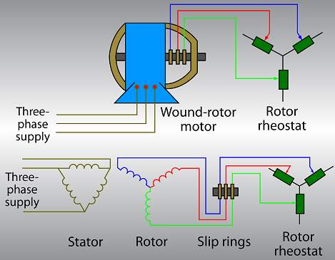
The stator windings of a wound rotor motor are three sets of windings connected 120 electrical degrees apart. These may be connected either wye or delta. The rotor is a laminated steel speed control equipment external to the rotor. These brushes are held in brush holders that are rigidly attached to the motor end bell assembly, or end cover.
Wound Rotor Speed Control
The insertion of resistance in the rotor circuit not only limits the starting surge of current, but also produces a high starting torque and provides a means of adjusting the speed. If the full resistance of the speed controller is cut into the rotor circuit when the motor is running, the rotor current decreases, and the motor slows down. As the rotor speed decreases, more voltage is induced in the rotor windings and an increase in rotor current is developed to create the necessary torque at the reduced rotor speed.
If all the resistance is removed from the rotor circuit, the current and the motor speed will increase. However, the rotor speed will always be less than the synchronous speed of the field developed by the stator windings. Recall that this fact is also true of the wound rotor induction motor.
Direct Current Motors
The operation of DC motors is based on the same principles as AC motors. A current-carrying conductor placed in a magnetic field perpendicular to the lines of flux will tend to move in a direction perpendicular to the magnetic lines of flux.
Operating Principles
Stated simply, DC motors rotate because of the two magnetic fields interacting with each other. The DC motor armature acts like an electromagnet when current flows through its coils. Since the armature (rotor) is located within the magnetic field of the field poles (stator poles), these two fluxes will interact. Like poles will repel each other and unlike poles will attract one another. The armature of a DC motor has windings on it that are connected to commutator segments. Figure 20 shows a DC motor field structure and armature assembly.
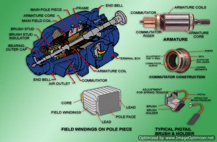
Armature Construction
The armature is a cylindrical iron structure mounted directly on the motor shaft. The armature windings are imbedded in slots in the surface of the armature, and the ends of the conductors that make up the windings terminate on copper segments on one end of the armature shaft. Current is applied to these windings through carbon brushes that press against the commutator segments. The commutator segments change the direction of current in the armature windings as they pass across the poles of opposite polarity. This results in continuous torque in one direction, which causes the armature to rotate.
DC Motor Ratings
DC motors are rated according to their voltage, current, speed, and horsepower output.
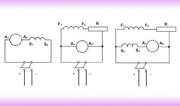
Types of DC Motors
There are three types of standard DC motors: series, shunt, and compound. Figure 21 shows the armature, and a shunt motor has the field winding in parallel with the armature. A compound motor has both a series and a shunt connected field winding.
Torque
Torque of the motor is the twisting force applied to the shaft of the motor by the magnetic field interaction between the armature. The magnitude of torque depends on the magnetic strengths of those two fields, which is then dependent on the current flowing through them.
Starting Current and Counter EMF
When a DC motor is in operation, it acts much like a DC generator. The stator produces a magnetic field (field poles), and a loop of wire in the induction motors. This induced voltage (EMF) causes a current to flow in them, and a resulting magnetic field is created.
Before analyzing the relative direction between the current induced in the armature windings and the current that caused it in the field poles, first remember the left-hand rule. Using your left hand, hold it so that your index finger points in the direction of the magnetic field (north to south) and your thumb points in the direction of rotational force on a given conductor. Your middle finger will now point in the direction of current flow for that conductor. This current would be in opposition to the current that is flowing from the battery. Since this induced voltage and induced current is opposite to that of the battery, it is called counter EMF. The two currents are flowing in opposite directions. This would mean that the battery voltage and the counter EMF are opposite in polarity.
When first discussing counter EMF, we began by disregarding the fact that external DC was being applied to the armature via the brushes. The induced voltage and resulting current flow was then shown to flow opposite to the externally applied current. This was an oversimplification, because only one current flows at a time. Since the counter EMF can never become as large as the external applied voltage, and since they are opposite in polarity, the counter EMF works to cancel only a part of the applied voltage. The single current that flows is smaller due to the counter EMF.
Since counter EMF of a motor is generated by the action of the armature windings cutting the lines of force set up by the field poles, the value of it will depend on the field strength and the armature speed.
The effective voltage acting in the armature is the applied voltage minus the counter EMF. Ohm
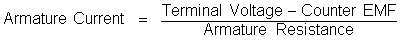
Example: Find the value of counter EMF of a DC motor when it is known that the terminal voltage is 240 V and the armature current is 60-amps. The armature resistance has been measured at .08 ohms.
| Answer: | |||
| Terminal Voltage | = | CEMF + (IA) (RA) | |
| CEMF | = | Terminal Voltage – (IA) (RA) | |
| = | 240 – (60 x .08) | ||
| = | 240 – 4.8 | ||
| = | 235.2 volts |
Starting Resistance
Large DC motors require that starting resistance be inserted in series with the motor armature. As seen by the previous equation, the current drawn by the motor reactance was high as was the case in AC starting current will be abnormally high unless limited by external starting resistance.
Figure 22 shows a shunt coil that is connected directly across a 250-volt line. The armature resistance is known to be 0.5 ohms. The full-load current of the motor is known to be 25 amps, and the shunt field current is 1 amp. The resulting armature current under full-load conditions would, therefore, be 24-amps.
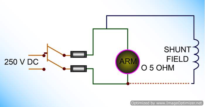
If starting resistance is not used, the value of armature current can be found using the following equation:
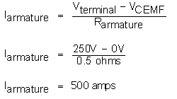
This amount of starting current is too high and may result in excessive torque and heat, which may cause damage to the motor. When starting resistance is added in series with the armature, the starting current can be limited to 1.5 times the full-load current value. After starting, this external resistance can be removed from service.
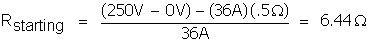
If we desire to limit starting current to 1.5 times the full-load value, we can solve for the size of resistance that would be required using the previous equations.
Rstarting = (Vterminal – VCEMF) – IARA
| Where: | ||||
| starting IA | = | 1.5 IA steady state | ||
| = | 1.5 x 24 amps | |||
| = | 36 amps |
At the moment of motor start, when the rotor is at standstill and the CEMF is zero, the series resistance will be:
To find the wattage required in the starting resistance watts loss is calculated by the I2R method:
Example: Find the power developed in both watts and horsepower in a DC motor that has a terminal voltage of 240 volts and an armature current of 60 amps. The armature resistance is known to be 0.08 ohms.
Answer:
Armature Reaction
When there is no current flowing through the armature of a DC motor, the magnetic line of flux created by the field poles is undistorted, as shown in Figure 23. The lines of flux run parallel from north to south.
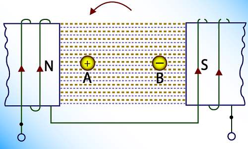
In this case, if a line were drawn in the center of the armature perpendicularly, this line would represent the neutral plane, or position where the lines of force would have the least effect.
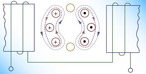
Figure 24 shows current flowing in the armature, but no current flowing in the main field windings. The resulting armature windings lines-of-flux surround the armature windings in a manner according to Fleming
When current flows in both the armature and in the main field windings, as shown in Figure 25, it is clear that the two fields interact. This interaction is called armature reaction. It tends to weaken the main field produced by the main field windings, distort the main field, and result in shifting the position of the neutral axis.
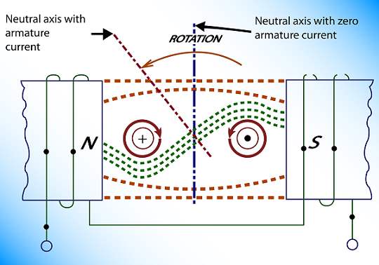
Armature reaction has a significant effect on the operation of DC motors as well as DC generators. The brushes on the commutator must be so mounted that they contact the commutator at the neutral plane under load. This is known as the running neutral plane. It is at this point that sparkless commutation can be best obtained, because at this position, the armature coil is undergoing commutation at a minimum flux. In DC motors, armature reaction may cause instability of speed with load variations and sparking at the brushes if they are not in the proper position. Compensating windings and interpoles are often used to counteract armature reaction.
Interpoles
Interpoles provide a commutating flux that generates an EMF necessary to neutralize the EMF of self-induction in the armature coils undergoing commutation. Since the field flux in the DC motor is distorted by the armature flux, the interpoles are of a polarity opposite that of the following main pole in the direction of armature rotation.
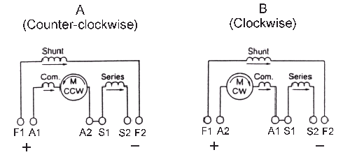
Direction of Rotation of DC Motors
The direction of rotation of a DC motor is dependent on the relative direction of current flow between the armature windings and the field windings. Reversing the direction of either of these windings will then change the direction of rotation of the motor. Simply reversing the input leads to a DC motor will not change the direction of rotation since the input is common to both the armature and the main field windings.
DC Shunt Motors
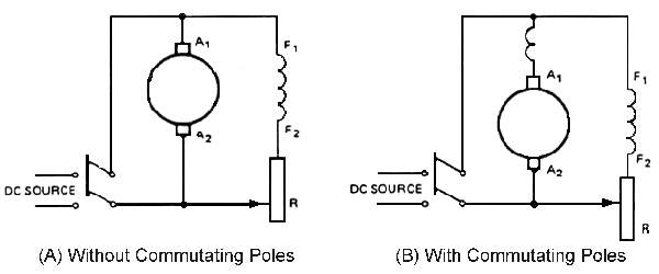
A shunt motor is a constant speed motor. If load is increased on a shunt motor, the motor speed will tend to decrease, causing a decrease in counter EMF, which will then result in an increase in armature current. This continues until the increase in current is enough to meet the increased torque requirements for the new load condition. The result is that the motor tends to stay in a state of constant equilibrium. Figure 26(A) shows a basic diagram of a shunt motor. Note that Figure 26(B) shows a winding in series with the armature. This winding has only a few turns in series with the armature and is there to counteract armature reaction.
It is important to note that the shunt field circuit of a DC motor should never be opened when the motor is operating, especially when unloaded. This is because an open field may cause the motor to rotate at dangerously high speeds. Large DC shunt motors have a field rheostat with a no-field release feature which disconnects the motor from the power source if the field circuit opens.
DC motors have excellent speed control. To operate the motor above rated speed, a field rheostat is used to reduce the field current and field flux. To operate below rated speed, resistors are used to reduce the armature voltage.
Torque
A DC shunt motor has high torque at any rated speed. At startup, a DC shunt motor can develop up to 150 percent of its normal running torque as long as the resistors in the starting circuit can withstand the heating effect of the current.
Speed Regulation
The speed regulation of a shunt motor drops from 5 to 10 percent from no-load to full-load. As a result, a shunt motor is superior to the series DC motor.
DC Series Motors
Torque
A DC series motor develops 500 percent of its full-load torque at starting. Therefore, this type of motor is used in applications where large amounts of starting torque are needed such as in cranes, railway applications, and other high starting torque demands. With a series motor, any increase in load causes an increase in both the armature current and the field current. Since torque depends on the interaction of these two flux fields, the torque increases as the square of the value of the current increases. Therefore, series motors produce greater torque than shunt motors for the same increase in current. The series motor shows a greater reduction in speed for an equal change in load.
Speed Control and Speed Regulation
The speed control of a series motor is poorer than that of a shunt motor because if the load is reduced, a simultaneous reduction of current occurs in both the armature and field windings, and therefore there is a greater increase in speed than would be in a shunt wound motor.
If the mechanical load were to be disconnected completely from a series motor, the motor would continue to accelerate until the motor armature self-destructed. For this reason, series wound motors are always permanently connected to their loads.
Varying the applied voltage controls the speed of a series DC motor. A series motor controller usually is designed to start, stop, reverse, and regulate speed. By reversing either the armature or the field winding current flow, you change the direction of rotation of a series motor.
Motor Ratings
Series DC motors are rated for voltage, current, horsepower, and maximum speed.
DC Compound Motors
Compound DC motors are used whenever it is necessary to obtain speed regulation characteristics not obtainable with either the shunt of series wound motor. Since many applications require high starting torque and constant speed under load, a compound motor is used. Some industrial applications include drives for elevators, stamping presses, rolling mills, and metal shears.
The compound motor has a normal shunt winding and a series winding on each field pole. They may be connected long shunt (Figure 27A) or short shunt (Figure 27B). When the series winding is connected to aid the shunt winding, the machine is a cumulative compound motor. When the series field opposes the shunt field, the machine is a differential compound motor. Based on practical experience, all compound DC motors are cumulatively compounded.
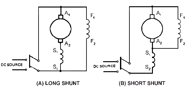
Torque
The operating characteristics of a cumulative compound wound motor are a combination of the series motor and the shunt motor. A cumulative compound wound motor develops high torque for sudden increases in load.
Speed
Unlike the series motor, a cumulative compound wound motor has definite no-load speeds. It will not build up self-destructive speeds if the load is removed. Inserting resistors in the armature circuit to reduce the applied voltage can control speed control of a cumulative compound wound motor.
When the motor is reversed frequently, such as for installations in elevators, hoists, and railways, the controller should have voltage dropping resistors and switching arrangements to reverse the motor direction.
Speed Regulation
The speed regulation of a cumulative compound wound motor is inferior to that of a shunt motor and superior to a series motor.
Industrial Applications
Synchronous motors rated at 20 hp or more are used for constant speed applications. They are used to drive large air and gas fans, blowers, and large pumps in water pumping stations.
Some industrial applications use three-phase synchronous motors to drive mechanical loads and correct power factor values. Figure 28 shows a typical industrial feeder. The feeder has a lagging power factor condition due to two induction motors. A synchronous motor is connected to this same feeder and is operated with an overexcited field. The synchronous motor supplies leading reactive kilovars to compensate for the lagging kilovars due to the induction motors or other inductive load on the same three-phase distribution system. The DC field of the synchronous motor can be over-excited enough to supply a value of leading kilovars equal to the lagging kilovars. As a result, the power factor of the distribution system is corrected to unity.
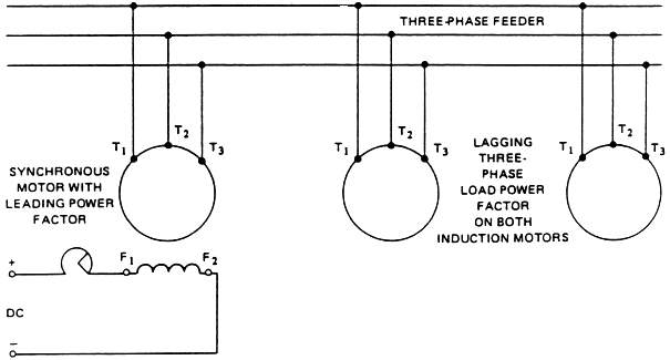
The synchronous motor may be used only to correct the power factor and not for driving any mechanical load. It then has the same function as a bank of capacitors. When used to correct the power factor only, the synchronous motor is called a synchronous capacitor or a synchronous condenser.
The following example shows how a synchronous motor is used to overcome the lagging kilovars due to induction motors on a three-phase distribution system.
Example: A three-phase, 220-volt feeder supplies two motors. One motor is a three-phase, wound rotor induction motor. It takes 40 amperes at 81 percent lag power factor. The other motor is a three-phase, synchronous motor that takes 30 amperes at 65 percent lead power factor. Determine the:
- Watts, volt-amperes, and lagging vars of the wound-rotor induction motor.
- Watts, volt-amperes, and leading vars of the synchronous motor.
- Total load, in kilowatts, supplied to the two motors.
- Power factor of the three-phase feeder circuit.
Solution:
1. The apparent power in volt amperes taken by the wound rotor induction motor is:
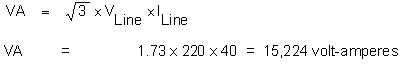
- The input in watts to the induction motor is:
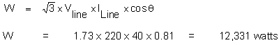
- The vars taken by the motor is:
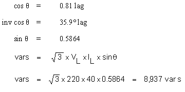
2. The apparent power, in volt amperes, taken by the synchronous motor is:
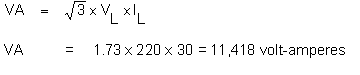
- The input in watts to the synchronous motor is:
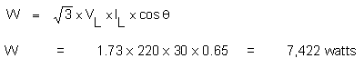
- The vars for the synchronous motor is:
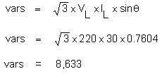
3. The total true power, in kilowatts, taken by the two motors in the arithmetic sum of the individual power values for the two motors:
| Total watts | = 12,331 + 7,422 | = 19,753 watts | = 19.753 kW |
4. The reactive power for the entire three-phase feeder is the difference between the lagging and leading vars:
| 8,937 lag – | 8,683 lead | = | 254 vars lag |
Thus, 254 vars of lagging quadrature power are not overcome by the synchronous motor. This value of lagging vars, combined with the total power in watts, gives the apparent power in volt-amperes:
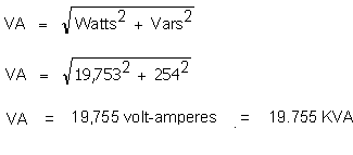
The power factor of the entire system is the ratio of the total true power, in kilowatts, to the total apparent power, in kilovolt-amperes:
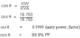
Connections and Terminal Markings for AC Motors
The markings on the external leads of an voltmeter with a range covering the motor operating voltage, and a means of measuring approximate resistance.

Rotation
A three-phase motor with three leads brought out can be connected to the line in any convenient way, and then if it rotates in the wrong direction, any two leads can be interchanged to correct the rotation. If the motor is connected to a gearbox or other mechanical load that might be damaged by improper rotation, the correct lead sequences should be determined by use of a phase rotation meter.
A two-phase motor with four leads may be lighted out to determine which leads belong to one phase. These two leads are then connected to one phase of the line and the other two leads to the other phase. If the motor rotates in the wrong direction, the two leads of either phase can be interchanged. The real problem comes with double-voltage and consequent-pole motors, which have more leads and circuits.
Double-Voltage Motors
Double-voltage motors can be either three-phase or two-phase and can be connected either wye or delta, depending on the manufacturer.
Three-Phase Star Connection
This type of motor has nine leads and four separate circuits, as shown in Figure 29. Three circuits have two leads each, and the fourth has three leads. The circuits should be tested out with a lamp or buzzer, and the three leads on a common circuit forming the internal star should be permanently tagged T7, T8, T9, in any order. The other leads should be temporarily tagged T1, T4 for one circuit; T2, T5 on the second circuit; and T3, T6 on the third circuit. It will be assumed here that in all cases of double voltage the motor is wound to operate on 220-440 volts, as this is the most common voltage range. For any other voltages, all of the following test voltages should be changed in proportion to the motor rating.
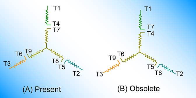
The motor may be started on 220 volts, with leads T7, T8, and T9 connected to the source of power and all other leads disconnected. If the motor is too large to be started by connecting it directly to the line, the starting voltage should be reduced as in the regular operation of the motor. With the motor running light, the voltage across each of the three open circuits should be measured. This voltage should be slightly under 127 volts and should be the same on all three circuits. With the motor still running, connect T7 to T4 and measure the voltage across leads T1 and T8, and also across leads T1 and T9. If these voltages are both the same value and equal about 335 volts, tags T1 and T4 should be marked permanently.
If the two voltages are of the same value and equal about 127 volts, interchange T1 and T4. If the voltage indications between terminals T1, T8 and T1, T9 are unequal, then disconnect T4 from T7 and connect T4 to T8, measuring the voltages between T1, T7 and T1, T9.
Changes and measurements should be made in this way until a position is found at which both voltages are equal and of a value of about 335 volts. With the motor still running light, and with leads T7, T8, T9 used as terminals, leads T4, T5, and T6 may be connected together and the voltage read between leads T1, T2, and T3. The voltage read should equal approximately 220 volts. For a further check, the motor should be shut down and reconnected, using leads T1, T2, and T3 as terminals, with T4, T5, and T6 connected together and leads T7, T8, and T9 disconnected. Care should be taken to connect the line that was on T7 to T1, the one that was on T8 to T2, and the one that was on T9 to T3. The direction of rotation should be the same as with the previous connection. The motor is now ready to operate on 220 volts by connecting T4, T5, and T6 together and using T1, T7 as one lead; T2, T8 as another; and T3, T9 as a third. By connecting T4 to T7, T5 to T8, and T6 to T9, and using T1, T2, and T3 as leads, the motor should operate on 440 volts.
The connection plate mounted on the motor may disagree with the lead markings as determined herein and shown on Figure 29, indicating that markings T4 and T7 are interchanged, as well as T5 and T8, and T6 and T9. Lead markings as shown in Figure 29A is the present NEMA® standard, whereas Figure 29B illustrates the lead marking as formerly used on some dual-voltage star connected motors. When remarking motor leads, it is recommended that the present standard marking be adhered to in every case, and, where necessary, the connection plate be revised or replaced.
Three-Phase Delta Connection
This motor will also have nine leads but only three separate circuits; three leads are connected to each circuit. In this case, it is also necessary to have an instrument for measuring resistance in addition to other equipment. Only comparative values, not actual values, are required. Such values can be obtained with a Wheatstone Bridge, or comparative results can be obtained by taking the voltage drop over the various parts of the circuit with a millivolt meter. There should be a constant value of direct current in the windings, which should not exceed the current rating of the motor.
It is necessary to find leads T1, T2, and T3, as shown in Figure 29. They can be found by an approximate measurement of resistance, since the resistance from T4 to T9 is twice that from T4 to T1. T2, and T3 are similarly located by corresponding measurements in the other circuits. These leads should then be permanently marked. The remaining leads in the circuit containing T1 should be temporarily marked T4 and T9; those in the same circuit with T2 should be marked T5 and T7; and those in the same circuit with T3 should be marked T8 and T6 in any order.
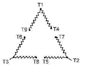
After leads T1, T2, and T3 have been located, the motor should be started and run on 220 volts, using T1, T4, and T9 as leads and leaving all other terminals disconnected. T4, T7 should then be connected together and the voltage read between T1 and T2. If this voltage equals approximately 440 volts, the marking is correct. If this voltage is approximately 380 volts, interchange T5 and T7 or T4 and T9 and measure the voltage again. If it is approximately 220 volts, interchange T5, T7, and T4, T9. When this voltage equals approximately 440 volts, mark T4, T9, T7, and T5 permanently, taking care that leads are marked T4 and T7 which, when connected together, gives 440 volts between T1 and T2. A similar procedure should then be followed, connecting T6 to T9 and measuring the voltage between T1 and T3. When the markings are all correct, the voltages between T1, T2, and T3 should equal approximately 440 volts.
As a check, the motor should be shut down and reconnected, using T2, T5, and T7 as leads. Care should be taken that T7 is attached to the line previously connected to T9, T2 attached to the line previously connected to T1, and T5 to the line previously connected to T4. When the motor is again started, the direction of rotation should be in the same direction as with the previous connection. If the direction of rotation is correct, the motor should again be reconnected using T3, T6, and T8 as leads and connecting the line from T5 to T6, the line from T2 to T3 and the line from T7 to T8.
When the motor is again started, the direction of rotation should be in the same direction as with the previous connections. When the above tests have been completed, the motor is ready to be connected permanently. If it is desired to run the motor on 220 volts, connect T6, T1, and T7 together and use them as one lead; T4, T2, and T8 as a second lead; and T3, T9, and T5 as a third lead. If it is desired to run the motor on 440 volts, connect T4 to T7, T5 to T8, and T6 to T9 using T1, T2, and T3 as leads. Permanent markings should be made on all leads.
Two-Phase Double-Voltage Connection
The two-phase, double-voltage motor can always be distinguished by its eight leads (see Figure 31). There are four separate circuits with two leads to a circuit. Trace out the circuits by a lamp or buzzer as in the previous case. Temporarily tag the leads on the first circuit T1, T5; those on the second circuit T2, T6; those on the third circuit T3, T7; and those on the fourth circuit T4, T8. Start the motor and run it single phase on 220 volts, using any pair of leads from a single circuit. To do so it will be necessary to bring the motor up to speed by externally applied power. The preferred method is by belting it to another motor. However, any available means of giving the motor a slight start is satisfactory, as it will come up to speed single phase if given a sufficient start. Connect T7 to T5 and measure the voltage from T1 to T3. If the voltage equals 440 volts, mark T1, T5, T3, and T7 permanently. If this voltage is zero, interchange either pair of leads.
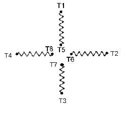
If the voltage measured equals approximately 310, disconnect T7 and try leads from another circuit until one is found that will give 440 volts from T1 to the lead on the other end of the circuit. When such a circuit is found, mark the leads permanently T1, T5, and T7, T3, being careful that leads marked T6 and T7 are those which, when connected, give 440 volts between T1 and T8. This procedure should then be followed with the other four leads, making final markings as shown in Figure 22.
When all the leads have been permanently marked, the motor may be connected for 440-volt operation by connecting T5 to T7, T6 to T8 and using T1, T3 as leads for one phase and T2, T4 as leads for the second phase. For operation on 220 volts, connect T1 to T7, T2 to T8, T3 to T5, and T4 to T6. Use T2, T8, and T4, T6 as leads on one phase and likewise for T3, T5, and T1, T7 as leads on the second phase.
Two-Speed Consequent-Pole Motors
An induction motor using the consequent-pole principle to obtain two speeds with a single winding requires that six leads be brought out. In this case, all leads are interconnected, so that it is not necessary to test for separate circuits. In the following discussion, it will be assumed that the motor is wound to run on 220-volts. If it is wound for any other voltage, the test voltages given should be changed in proportion to the change in rating.
Star Connection
The star-connected motor shown in Figure 32 is used for variable torque ratings having a high-speed horsepower rating four times the low-speed horsepower rating. If this fact is not apparent from the nameplate reading, the motor can be identified as star-connected by measuring the resistance between the various leads.
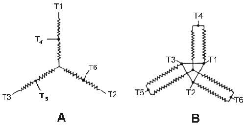
Referring to Figure 32A, it can be seen that regardless of between which two leads the resistance is measured, a relative value of either 1, 2, 3, or 4 must be obtained. For example, if the resistance between T1 and T4 is 1, then between T4 and T6, the resistance will be 2; between T1 and T6, it will be 3, and between T1 and T2, it will be 4. Hence, the three leads having the highest resistance (relative value of 4) between them should be located and permanently marked T1, T2, and T3. Then, the resistance between T1 and each of the remaining three unmarked leads should be measured, and the lead that gives lowest resistance (relative value of 1) should be marked T4. Similarly, the resistance between lead T2 and each of the two remaining unmarked leads should be measured, and the lead that gives a relative resistance of 1 should be marked T6. The final remaining lead should be marked T5.
With the lead marking determined, it should then be checked by running the motor at normal voltage, with T1, T2, and T3 connected to the line and leads T4, T5, and T6 left open. The motor should run at its normal slow speed, this being the series star connection shown in Figure 32A. The direction of rotation should be noted.
Finally, leads T1, T2, and T3 should be connected together and leads T4, T5, and T6 connected to the line, with T4 to the same line lead previously used for T1, T5, the line lead previously used for T2, and T6 to the lead used for T3. The motor should run at its normal high speed and have the same direction of rotation as before, this being the parallel-star connection shown in Figure 32B.
Delta Connection
The delta-connected motor shown in Figure 33 for constant torque ratings has a high speed horsepower rating twice the low-speed horsepower rating. It can be distinguished from the star-connected motor by measuring the resistances. Referring to Figure 33A, it can be seen that regardless of between which two leads the resistance is measured, a relative value of either 1, 1.6, or 1.8 must be obtained. For example, if the resistance between T1 and T6 is 1, then between T1 and T5 it must be 1.8. The lowest value of resistance obtainable (relative value of 1) between any two leads should be found, and if the motor is delta-connected, it will be possible to go through all the leads measuring the lowest value of resistance from lead to lead, and ending up at the lead at which the start was made.
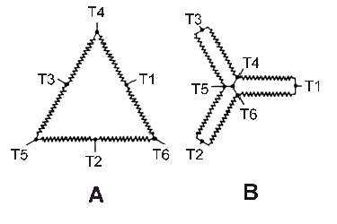
Start with the first pair of leads that give the lowest resistance (relative value of 1) between terminals, mark them temporarily T1 and T6. The lead should then be found which will give a resistance to T6 equal to that between T6 and T1. When this lead is found, it should be marked T2. The lead should then be found which will give the same resistance to T2 as that between T2 and T6, and this lead should be marked T5. This procedure should be followed until all the leads have been used. They should be marked from the beginning and in the order in which they are found T1, T6, T2, T5, T3, and T4. When all leads have been marked as described, the motor should be started and run single phase, applying 110 volts across T1 and T6. The voltage should then be measured between T1 and T2, between T2 and T3, and between T3 and T1. If each of these readings is 220 volts, then the leads are correctly marked and the markings should be permanently affixed. If these readings are 110 volts, then permanently re-mark all leads, changing T6 to T1, T2 to T6, T5 to T2, T3 to T5, T4 to T3, and T1 to T4. Start up again and with 110 volts single-phase impressed on T1 and T6, check the voltage from T1 to T2, from T2 to T3, and from T3 to T1, each of which should equal 220 volts.
To operate the motor at slow speed, use T1, T2, and T3 as line leads with leads T4, T5, and T6 disconnected, giving a series delta connection as shown in Figure 33A. Note the direction of rotation.
To operate at high speed, connect leads T1, T2, and T3 together and connect T4, T5, and T6 to the line, using the same line lead for T4 as previously used for T1, similarly for T5 and T2 and for T6 and T3. This should give the same direction of rotation as on previous slow speed operation and is the parallel-star connection shown in Figure 33B.
Delta Connection for Constant-Horsepower
The delta-connected motor for constant horsepower has the same relative resistances between leads as its constant-torque counterpart; hence, it can be distinguished from the latter only by observing the nameplate rating. The determination of proper lead marking for the two types of connections is essentially the same.
Referring to Figure 34, first locate any pair of leads that give the lowest resistance between terminals and temporarily mark them T4 and T1. The lead should then be found which gives a resistance to T1 equal to that between T4 and T1, and this lead should be marked T6. The lead should then be found that gives a resistance to T6 equal to that between T6 and T1, this lead being marked T2. This procedure should be followed until all the leads are used, and they should be temporarily marked from the beginning and in the order in which they are found as T4, T1, T6, T2, T5, and T3.
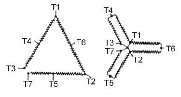
When all leads have been marked as described, the motor should be started and run single phase with 110 volts impressed across T4 and T1. The voltage should then be measured between T4 and T6, between T6 and T5, and between T5 and T4. If each of these readings is 220 volts, then the leads are correctly marked and the markers should be permanently affixed. If these readings are 110 volts, then permanently re mark all leads, changing T1 to T4, T6 to T1, T2 to T6, T5 to T2, T3 to T5, and T4 to T3. Start up again, and with 110 volts single phase applied across leads T4 and T1, check the voltage between T4 and T6, between T6 and T5, and between T5 and T4. Each reading should now be 220 volts.
To operate the motor at high speeds, connect leads T4, T5, and T6 to the line with leads T1, T2, and T3 disconnected, giving the series-delta connection shown in Figure 34A. Note the direction of rotation.
To operate the motor at slow speed, connect leads T4, T5, and T6 together and T1, T2, and T3 to the line, using the same line lead for T1 as previously used to T4, and similarly for T2 and T5 and for T3 and T6. This should give the same direction of rotation as obtained in previous high-speed operation and is the parallel-star connection shown in Figure 34B.
Open-Delta Connection Constant-Torque
The open-delta connection is frequently used for consequent-pole motors, particularly for four-speed, two-winding motors to avoid the possibility of harmful circulating currents being induced in the idle winding while the other is energized. The connections are identical to the previously discussed closed-delta connections, except that one corner of the delta is opened and an extra lead, T7, is provided.
Figure 35 shows the lead markings for the open-delta constant-torque connection. There are six relative values of resistance between leads, these being 1, 2, 3, 4, 5, or 6, depending upon which pair of leads is used. First, locate the pair of leads that give the highest resistance (value of 6) and mark these leads T3 and T7. Then, the lead should be located that gives the lowest resistance (relative value of 1) to T3, and this lead should be marked T4. Then the unmarked lead should be located that gives the lowest resistance (relative value of 1) to T4, and this lead should be marked T1. This procedure should be followed until all leads are used, and they should be marked from the beginning and in the order in which they are found as T3, T4, T1, T6, T2, T5, and ending with T7. The connections for a two-speed motor are shown in Figure 35.
For a four-speed motor, the second winding is marked identically to the first, except that ten is added to each lead number; that is, T1 will be T11, T2 will be T12, etc. After first determining which leads belong to a common winding by ringing or lighting out the two separate circuits, lead identification can proceed as outlined above. The winding containing leads T1 through T7 will give the lowest and next to highest speeds; the winding containing leads T11 through T17 will give the highest and next to lowest speeds.
Open-Delta, Constant-Horsepower
Figure 36 shows the lead markings for the open-delta constant-horsepower connection. Relative resistances, procedure for lead identification, marking of the second winding in a four-speed two-winding motor, and the relative speeds provided by the two windings are all identical to the constant-torque motor except that the sequence around the open-delta is T5, T3, T4, T1, T6, T2, and T7, with low and high-speed connections as shown in Figure 36.
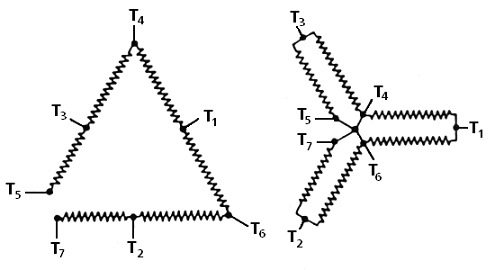
Direct Current Motor Directional Connections
Terminal markings are used to tag only those terminals to which connections must be made from outside circuits or from auxiliary devices that must be disconnected for shipment. The subscript numerals indicate the direction of current flow in the windings. That is, with a standard direction of shaft rotation and polarity, the current in all windings will be flowing from 1 or 2 or from a lower to a higher subscript numeral. In DC machines, A1 and A2 always indicate the armature leads, S1 and S2 the series-field leads, and F1 and F2 the shunt-field leads.
Direct Current Shunt Motors
The standard direction of shaft rotation for DC motors is clockwise facing the drive end. To obtain standard direction of shaft rotation, the motor must be connected to the line in such a way that the current will flow through the first winding from 1 to 2, then to 1 of the next winding in the proper sequence. One of the first winding is connected to one side of the line, and 2 of the last winding is connected on the other side of the line (see Figure 37).
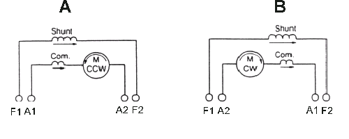
When leads F1 and A1 of Figure 37A are connected to the plus side of the line, the current flow will be from 1 to 2. The direction of rotation will be standard, or counter-clockwise. To obtain a clockwise direction of shaft rotation, it is necessary to reverse either the shunt-field leads F1 and F2 or the armature leads A1 and A2, as shown in Figure 37B, but not both.
Series-Wound Motors
When lead A1 is connected to the plus side of the line and lead A2 connected to lead S1, the current will flow from a lower number to a higher number in succeeding windings. Thus, a standard counter-clockwise direction of shaft rotation will be obtained as shown in Figure 38A. To obtain a clockwise direction of shaft rotation, it is necessary to reverse either the series-field leads S1 and S2 or the armature leads A1 and A2, as shown in Figure 38B, but not both.
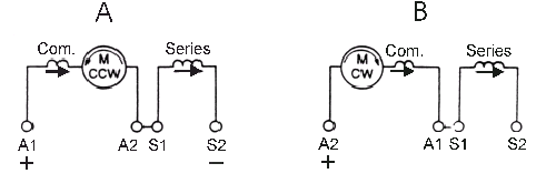
Direct Current Compound-Wound Motor
In compound machines, the series field is always tagged such that when current flows from 1 to 2, a cumulative field is produced. Hence, when leads F1 and A1 are connected to the plus side of the line and lead A2 connected to S1, the direction of current flow will be from a lower number to a higher number in each winding. Thus, a standard counter-clockwise direction of rotation is obtained, as shown in Figure 39A. To obtain a clockwise direction of shaft rotation, reverse either the armature leads A1, A2, as shown in Figure 39B, or both the shunt and series-field leads F1, F2 and S1, S2. It is necessary to reverse both shunt and series fields in a compound machine. If this is not done, the resulting connection will be opposite the former connection. For example, if the connection were cumulative compound, it would now be differential compound, and vice versa.