AC Generation
A generator is a device that converts mechanical energy into electrical energy. AC generators use induction to create an alternating electrical current. An understanding of how an AC generator develops an AC output will help you understand the AC power generation process test.
Elementary AC Generators
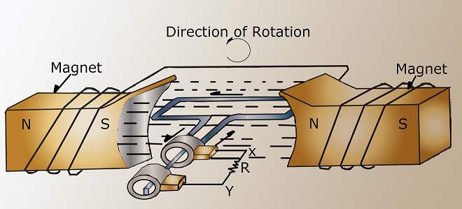
An elementary AC generator ('''Figure 1''') consists of a conductor, or loop of wire, that rotates in a magnetic field. In this example, the magnetic field is produced by an electromagnet connected to a DC power source. The two ends of the loop are connected to slip rings, and they are in contact with two brushes. When an outside mechanical force rotates the loop, it cuts magnetic lines of force, first in one direction and then the other.
Development of a Sine Wave Output
At the instant the loop is in the vertical position ('''Figure 2''', 0°), the coil sides are moving parallel to the field and do not cut magnetic lines of force. In this instant, there is no voltage induced in the loop. As the coil rotates in a clockwise direction, the coil sides will cut the magnetic lines of force in opposite directions. The direction of the induced voltages depends on the direction of movement of the coil.
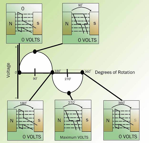
The induced voltages add in series, making slip ring X ('''Figure 1''') positive (+) and slip ring Y negative (-). The potential across resistor R will cause a current to flow from Y to X through the resistor. This current will increase until it reaches a maximum value when the coil is horizontal to the magnetic lines of force ('''Figure 2''', 90°). The horizontal coil is moving perpendicular to the field and is cutting the greatest number of magnetic lines of force. As the coil continues to turn, the voltage and current induced decrease until they reach zero, where the coil is again in the vertical position ('''Figure 2''', 180°). In the other half revolution, an equal voltage is produced except that the polarity is reversed ('''Figure 2''', 270°, 360°). The current flow through R is now from X to Y ('''Figure 1''').
The periodic reversal of polarity results in the generation of a voltage, as shown in '''Figure 2'''. The rotation of the coil through 360° results in an AC sine wave output.
AC Generation Analysis
Analysis of the AC power generation process and of the alternating current we use is necessary to better understand how AC power is used in today's technology.
The output voltage of an AC generator can be expressed in two ways. One is graphically by use of a sine wave ('''Figure 3'''). The second way is algebraically by the equation e = Emax sin ωt, which is covered later in the text.
When a voltage is produced by an AC generator, the resulting current varies in step with the voltage. As the generator coil rotates 360°, the output voltage goes through one complete cycle. In one cycle, the voltage increases from zero to Emax in one direction, decreases to zero, increases to Emax in the opposite direction (negative Emax), and then decreases to zero again. The value of Emax occurs at 90°, and is referred to as peak voltage. The time it takes for the generator to complete one cycle is called the ''period'', and the number of cycles per second is called the ''frequency'' (measured in hertz).
One way to refer to AC voltage or current is by peak voltage (Ep) or peak current (Ip). This is the maximum voltage or current for an AC sine wave.
Another value, the peak-to-peak value (Ep-p or Ip-p), is the magnitude of voltage, or current range, spanned by the sine wave. However, the value most commonly used for AC is effective value. Effective value of AC is the amount of AC that produces the same heating effect as an equal amount of DC. In simpler terms, one ampere effective value of AC will produce the same amount of heat in a conductor, in a given time, as one ampere of DC.
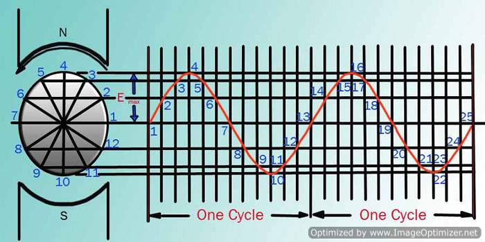
The heating effect of a given AC current is proportional to the square of the current. Effective value of AC can be calculated by squaring all the amplitudes of the sine wave over one period, taking the average of these values, and then taking the square root. The effective value, being the root of the mean (average) square of the currents, is known as the root-mean-square, or RMS value. To understand the meaning of effective current applied to a sine wave, refer to '''Figure 4'''.

The values of I are plotted on the upper curve, and the corresponding values of I2 are plotted on the lower curve. The I2 curve has twice the frequency of I and varies above and below a new axis. The new axis is the average of the I2 values, and the square root of that value is the RMS, or effective value, of current. The average value is 2Imax2. The RMS value is then:

which is equal to 0.707 Imax.
The instantaneous value is the current or voltage at any particular instance in time. This value can be anywhere from zero to the peak value, depending upon the time chosen to look at it.
There are six basic equations that are used to convert a value of AC voltage or current to another value, as listed below:
- Average value = peak value x 0.637
- Effective value (RMS) = peak value x 0.707
- Peak value = average value x 1.57
- Effective value (RMS) = average value x 1.11
- Peak value = effective value (RMS) x 1.414
- Average value = effective (RMS) x 0.9
The values of current (I) and voltage (E) that are normally encountered are assumed to be RMS values; therefore, no subscript is used.
Another useful value is the average value of the amplitude during the positive half of the cycle. The following equation is the mathematical relationship between Iav, Imax, and I.
Iav = 0.6371max = 0.90I
The following equation is the mathematical relationship between Eav, Emax, and E.
Eav = 0.6371max = 0.90E
Example 1: The peak value of voltage in an AC circuit is 200 V. What is the RMS value of the voltage?
E = 0.707 Emax E = 0.707 (200 V) E = 141.4 V
Example 2: The peak current in an AC circuit is 10 amps. What is the average value of current in the circuit?
Iav = 0.637 Imax Iav = 0.637 (10 amps) Iav = 6.37 amps
AC Generator Components
AC generators are widely used to produce AC voltage. To understand how these generators operate, the function of each component of the generator must first be understood.
Field
The field in an AC generator consists of coils of conductors within the generator that receive a voltage from a source (called ''excitation'') and produce a magnetic flux. The magnetic flux in the field cuts the armature to produce a voltage. This voltage is ultimately the output voltage of the AC generator.
Armature
The armature is the part of an AC generator in which voltage is produced. This component consists of many coils of wire that are large enough to carry the full-load current of the generator.
Prime Mover
The prime mover is the component that is used to drive the AC generator. The prime mover may be of any type of rotating machine, such as a diesel engine, a steam turbine, or a motor.
Rotor
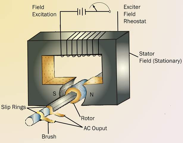
The rotor of an AC generator is the rotating component of the generator, as shown in '''Figure 5'''. The rotor is driven by the generator's prime mover, which may be a field. The rotor will be the armature if the voltage output is generated there; the rotor will be the field if the field excitation is applied there.
Stator
The stator of an AC generator is the part that is stationary (refer to '''Figure 5'''). Like the rotor, this component may be the armature or the field, depending on the type of generator. The stator will be the armature if the voltage output is generated there; the stator will be the field if the field excitation is applied there.
Slip Rings
Slip rings are electrical connections that are used to transfer power to and from the rotor of an AC generator (refer to '''Figure 5'''). The slip ring consists of a circular conducting material that is connected to the rotor windings and insulated from the shaft. Brushes ride on the slip ring as the rotor rotates. The electrical connection to the rotor is made by connections to the brushes.
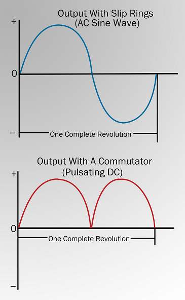
Slip rings are used in AC generators because the desired output of the generator is a sine wave. In a DC generator, a commutator was used to provide an output whose current always followed in the positive direction, as shown in '''Figure 6'''. This was not necessary for an AC generator. Therefore, an AC generator may use slip rings, which allow the output current and voltage to oscillate through positive and negative values. This oscillation of voltage and current takes the shape of a sine wave.
Three-Phase Circuits
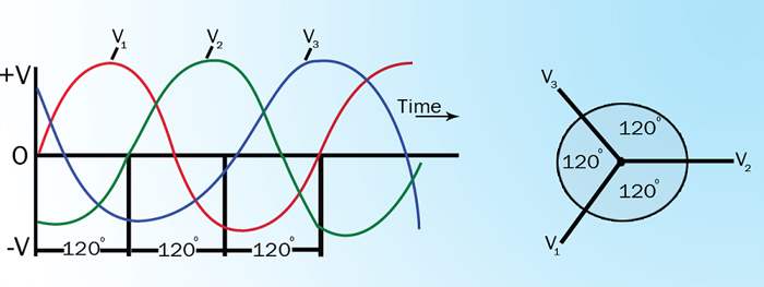
The design of three-phase AC circuits lends itself to a more efficient method of producing and using an AC voltage. A three-phase (3φ) system is a combination of three single-phase systems. In a 3φ balanced system, power comes from a 3φ AC generator that produces three separate and equal voltages, each of which is 120° out of phase with the other voltages ('''Figure 7''').
Advantages of using three-phase equipment (motors, transformers, etc.) are:
- Less weight than single-phase equipment of the same power rating
- A wider range of voltages
- Can be used for single-phase loads
- Three-phase power transmission lines are comparatively less expensive for the maximum number of lines needed for three single-phase systems.