AC Generation
An understanding of how an AC generator develops an AC output will help the student analyze the AC power generation process.
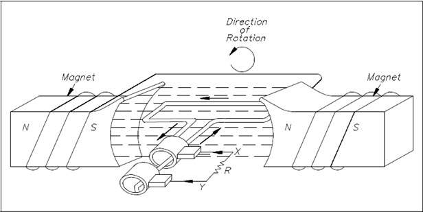
The elementary AC generator (Figure 1) consists of a conductor, or loop of wire in a magnetic field that is produced by an electromagnet. The two ends of the loop are connected to slip rings, and they are in contact with two brushes. When the loop rotates it cuts magnetic lines of force, first in one direction and then the other.
Development of a Sine-Wave Output
At the instant the loop is in the vertical position (Figure 2, 0°), the coil sides are moving parallel to the field and do not cut magnetic lines of force. In this instant, there is no voltage induced in the loop. As the coil rotates in a counter-clockwise direction, the coil sides will cut the magnetic lines of force in opposite directions. The direction of the induced voltages depends on the direction of movement of the coil.
The induced voltages add in series, making slip ring X (Figure 1) positive (+) and slip ring Y (Figure 1) negative (-). The potential across resistor R will cause a current to flow from Y to X through the resistor. This current will increase until it reaches a maximum value when the coil is horizontal to the magnetic lines of force (Figure 2, 90°). The horizontal coil is moving perpendicular to the field and is cutting the greatest number of magnetic lines of force. As the coil continues to turn, the voltage and current induced decrease until they reach zero, where the coil is again in the vertical position (Figure 2, 180°). In the other half revolution, an equal voltage is produced except that the polarity is reversed (Figure 2, 270° 360°). The current flow through R is now from X to Y (Figure 1).
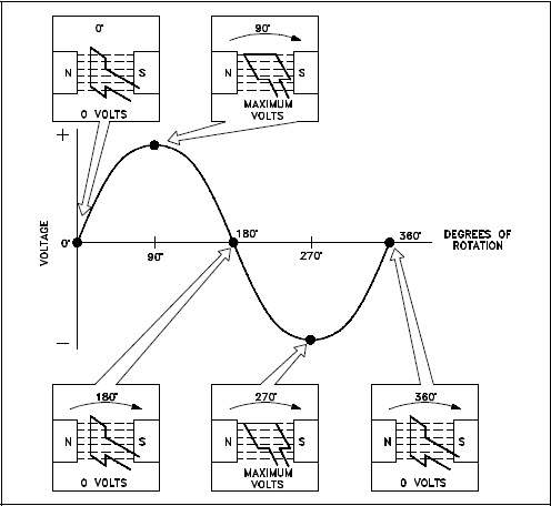
The periodic reversal of polarity results in the generation of a voltage, as shown in Figure 2. The rotation of the coil through 360° results in an AC sine wave output.
AC Generation Analysis
Analysis of the AC power generation process and of the alternating current we use in almost every aspect of our lives is necessary to better understand how AC power is used in todays technology.
Effective Values
The output voltage of an AC generator can be expressed in two ways. One is graphically by use of a sine wave (Figure 3). The second way is algebraically by the equation e = Emax sin ωt, which will be covered later in the text.
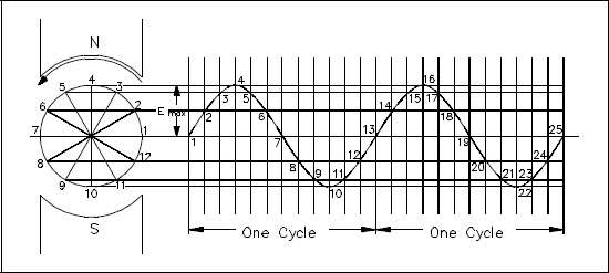
When a voltage is produced by an AC generator, the resulting current varies in step with the voltage. As the generator coil rotates 360°, the output voltage goes through one complete cycle. In one cycle, the voltage increases from zero to Emax in one direction, decreases to zero, increases to Emax in the opposite direction (negative Emax), and then decreases to zero again. The value of Emax occurs at 90° and is referred to as peak voltage. The time it takes for the generator to complete one cycle is called the period, and the number of cycles per second is called the frequency (measured in hertz).
One way to refer to AC voltage or current is by peak voltage (Ep) or peak current (Ip). This is the maximum voltage or current for an AC sine wave.
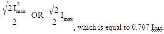
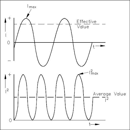
Another value, the peak-to-peak value (Ep-p or Ip-p), is the magnitude of voltage, or current range, spanned by the sine wave. However, the value most commonly used for AC is effective value. Effective value of AC is the amount of AC that produces the same heating effect as an equal amount of DC. In simpler terms, one ampere effective value of AC will produce the same amount of heat in a conductor, in a given time, as one ampere of DC. The heating effect of a given AC current is proportional to the square of the current. Effective value of AC can be calculated by squaring all the amplitudes of the sine wave over one period, taking the average of these values, and then taking the square root. The effective value, being the root of the mean (average) square of the currents, is known as the root-mean-square, or RMS value. In order to understand the meaning of effective current applied to a sine wave, refer to Figure 4.
The values of I are plotted on the upper curve, and the corresponding values of I2 are plotted on the lower curve. The I2 curve has twice the frequency of I and varies above and below a new axis. The new axis is the average of the I2 values, and the square root of that value is the RMS, or effective value, of current. The average value is Imax2. The RMS value is then
There are six basic equations that are used to convert a value of AC voltage or current to another value, as listed below.
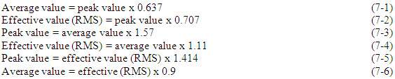
The values of current (I) and voltage (E) that are normally encountered are assumed to be RMS values; therefore, no subscript is used.
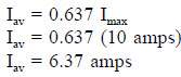
Another useful value is the average value of the amplitude during the positive half of the cycle. Equation (7-7) is the mathematical relationship between Iav, Imax, and I.

Equation (7-8) is the mathematical relationship between Eav, Emax, and E.

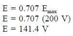
Example 1: The peak value of voltage in an AC circuit is 200 V. What is the RMS value of the voltage?
Example 2: The peak current in an AC circuit is 10 amps. What is the average value of current in the circuit?
Phase Angle
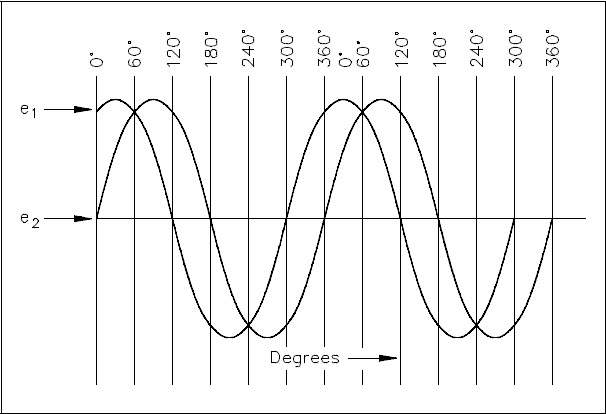
Phase angle is the fraction of a cycle, in degrees, that has gone by since a voltage or current has passed through a given value. The given value is normally zero. Referring back to Figure 3, take point 1 as the starting point or zero phase. The phase at Point 2 is 30°, Point 3 is 60°, Point 4 is 90°, and so on, until Point 13 where the phase is 360°, or zero. A term more commonly used is phase difference. The phase difference can be used to describe two different voltages that have the same frequency, which pass through zero values in the same direction at different times. In Figure 5, the angles along the axis indicate the phases of voltages e1 and e2 at any point in time. At 120°, e1 passes through the zero value, which is 60° ahead of e2 (e2 equals zero at 180°). The voltage e1 is said to lead e2 by 60 electrical degrees, or it can be said that e2 lags e1 by 60 electrical degrees.
Phase difference is also used to compare two different currents or a current and a voltage. If the phase difference between two currents, two voltages, or a voltage and a current is zero degrees, they are said to be “in-phase.” If the phase difference is an amount other than zero, they are said to be “out-of-phase.”
Voltage Calculations
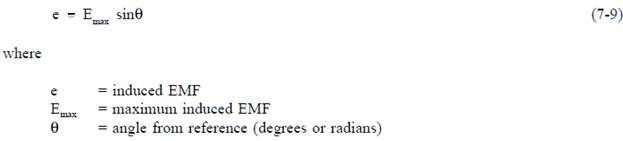
Equation (7-9) is a mathematical representation of the voltage associated with any particular orientation of a coil (inductor).
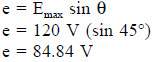
Example 1: What is the induced EMF in a coil producing a maximum EMF of 120 V when the angle from reference is 45°?
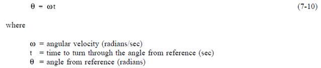
The maximum induced voltage can also be called peak voltage Ep. If (t) is the time in which the coil turns through the angle (Θ), then the angular velocity (ω) of the coil is equal to Θ/t and is expressed in units of radians/sec. Equation (7-10) is the mathematical representation of the angular velocity.
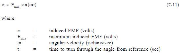
Using substitution laws, a relationship between the voltage induced, the maximum induced voltage, and the angular velocity can be expressed. Equation (7-11) is the mathematical representation of the relationship between the voltage induced, the maximum voltage, and the angular velocity, and is equal to the output of an AC Generator.
Current Calculations
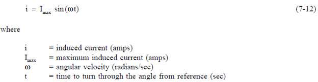
Maximum induced current is calculated in a similar fashion. Equation (7-12) is a mathematical representation of the relationship between the maximum induced current and the angular velocity.
Frequency Calculations
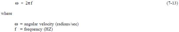
The frequency of an alternating voltage or current can be related directly to the angular velocity of a rotating coil. The units of angular velocity are radians per second, and 2π radians is a full revolution. A radian is an angle that subtends an arc equal to the radius of a circle. One radian equals 57.3 degrees. One cycle of the sine wave is generated when the coil rotates 2π radians. Equation (7-13) is the mathematical relationship between frequency (f) and the angular velocity (ω) in an AC circuit.
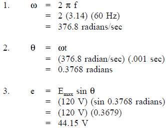
Example 1: The frequency of a 120 V AC circuit is 60 Hz. Find the following:
- Angular velocity
- Angle from reference at 1 msec
- Induced EMF at that point
Solution: