Basic DC Circuit Calculations
Each type of DC circuit contains certain characteristics that determine the way its voltage and current behave. To begin analysis of the voltages and currents at each part of a circuit, an understanding of these characteristics is necessary.
Series Resistance
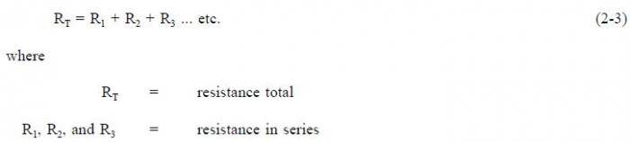
The total resistance in a series circuit is equal to the sum of all the parts of that circuit, as shown in equation (2-3).
Example:
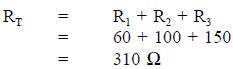
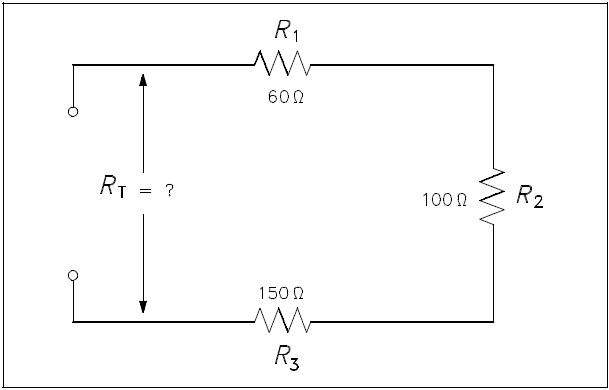
A series circuit has a 60Ω, a 100Ω, and a 150Ω resistor in series (Figure 1). What is the total resistance of the circuit?
Solution:
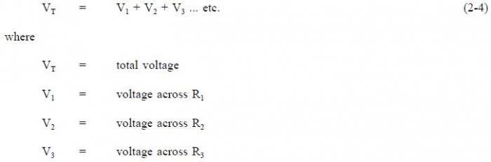
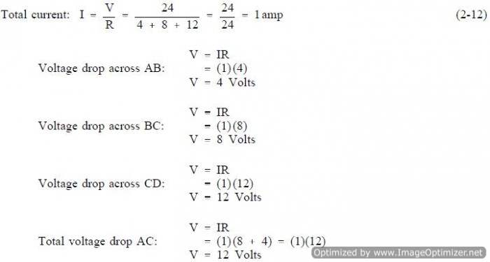
The total voltage across a series circuit is equal to the sum of the voltages across each resistor in the circuit (Figure 2) as shown in equation (2-4).
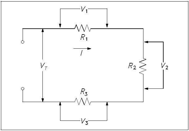
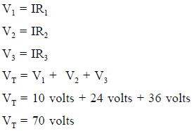
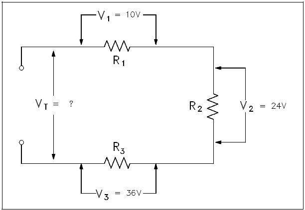
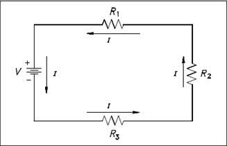
Ohms law may now be applied to the entire series circuit or to individual component parts of the circuit. When used on individual component parts, the voltage across that part is equal to the current times the resistance of that part. For the circuit shown in Figure 3, the voltage can be determined as shown below.
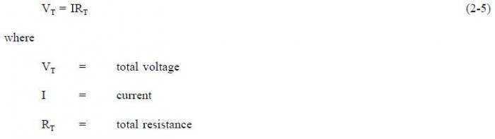
To find the total voltage across a series circuit, multiply the current by the total resistance as shown in equation (2-5).
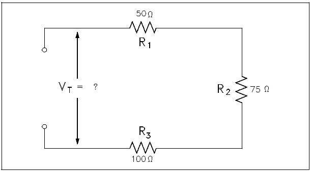
Example 1: A series circuit has a 50Ω, a 75Ω, and a 100Ω resistor in series (Figure 4). Find the voltage necessary to produce a current of 0.5 amps.
Solution:
Step 1: Find circuit current. As we already know, current is the same throughout a series circuit, which is already given as 0.5 amps.
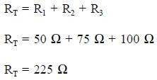
Step 2: Find RT.
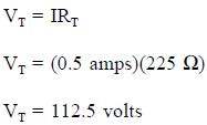
Step 3: Find VT. Use Ohms law.
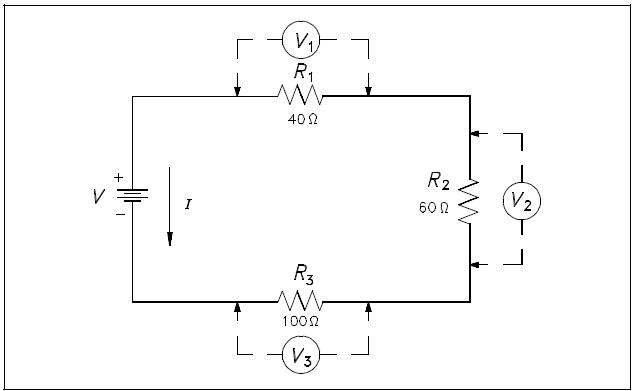
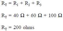
Example 2: A 120 V battery is connected in series with three resistors: 40Ω, 60Ω, and 100Ω (Figure 5). Find the voltage across each resistor.
Solution:
Step 1: Find total resistance.
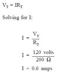
Step 2: Find circuit current (I).
Step 3: Find the voltage across each component.
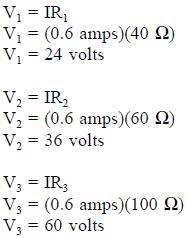
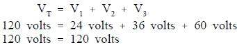
The voltages of V1, V2, and V3 in Example 2 are known as “voltage drops” or “IR drops.” Their effect is to reduce the available voltage to be applied across the other circuit components. The sum of the voltage drops in any series circuit is always equal to the applied voltage. We can verify our answer in Example 2 by using equation (2-4).
Parallel Currents
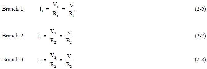
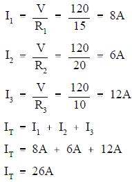
The sum of the currents flowing through each branch of a parallel circuit is equal to the total current flow in the circuit. Using Ohms Law, the branch current for a three branch circuit equals the applied voltage divided by the resistance as shown in equations (2-6), (2-7), and (2-8).
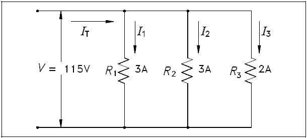
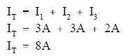
Example 1: Two resistors, each drawing 3A, and a third resistor, drawing 2A, are connected in parallel across a 115 volt source (Figure 6). What is total current?
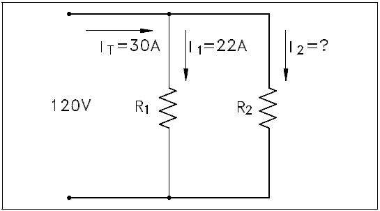
Example 2: Two branches, R1 and R2, are across a 120 V power source. The total current flow is 30 A (Figure 7). Branch R1 takes 22 amps. What is the current flow in Branch R2?

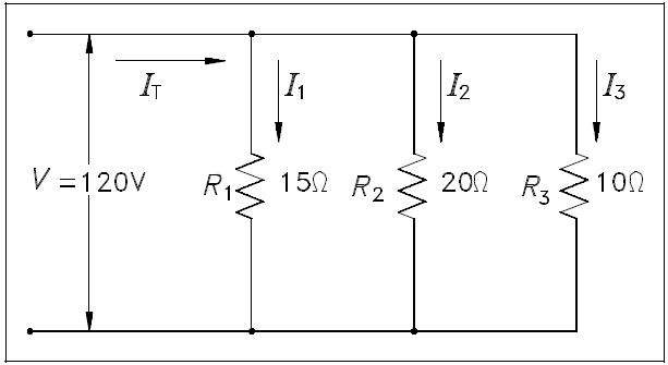
Example 3: A parallel circuit consists of R1 = 15Ω, R2 = 20Ωand R3 = 10Ω, with an applied voltage of 120 V (Figure 8). What current will flow through each branch?
Resistance in Parallel
Total resistance in a parallel circuit can be found by applying Ohms Law. Divide the voltage across the parallel resistance by the total line current as shown in equation (2-9).

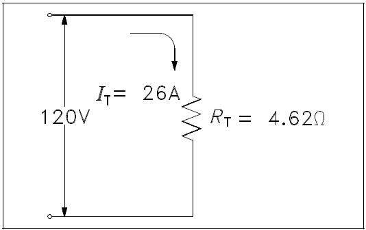
Example: Find the total resistance of the circuit shown in Figure 8 if the line voltage is 120 V and total current is 26A.
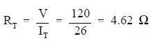
The total load connected to a 120 V source is the same as the single “equivalent resistance” of 4.62Ωconnected across the source (Figure 9). Equivalent resistance is the total resistance a combination of loads present to a circuit.
The total resistance in a parallel circuit can also be found by using the equation (2-10).

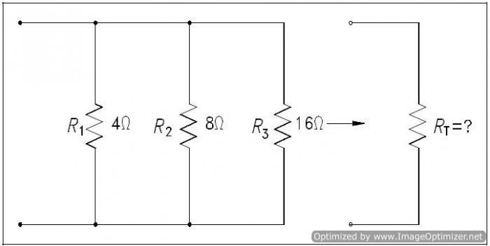
Example 1: Find the total resistance of a 4Ω, an 8Ω, and a 16Ωresistor in parallel (Figure 10).
Solution:
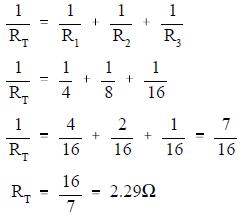
Note: Whenever resistors are in parallel, the total resistance is always smaller than any single branch.
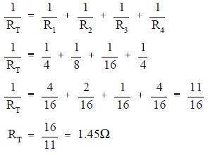
Example 2: Now add a fourth resistance of 4Ωin parallel to the circuit in Figure 11. What is the new total resistance of the circuit?
Solution:
Simplified Formulas
Total resistance of equal resistors in a parallel circuit is equal to the resistance of one resistor divided by the number of resistors.
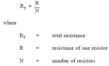
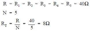
Example: Five lamps, each with a resistance of 40Ω, are connected in parallel. Find total resistance.
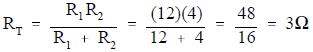
When any two resistors are unequal in a parallel circuit, it is easier to calculate RT by multiplying the two resistances and then dividing the product by the sum, as shown in equation (2-11). As shown in equation (2-11), this is valid when there are only two resistors in parallel.

Example: Find the total resistance of a parallel circuit which has one 12Ωand one 4Ω resistor.
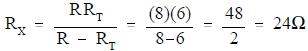
In certain cases involving two resistors in parallel, it is useful to find an unknown resistor, Rx, to obtain a certain RT. To find the appropriate formula, we start with equation (2-10) and let the known resistor be R and the unknown resistor be Rx.
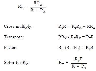
Example: What value of resistance must be added, in parallel, with an 8Ωresistor to provide a total resistance of 6Ω(Figure 11)?

Solution:
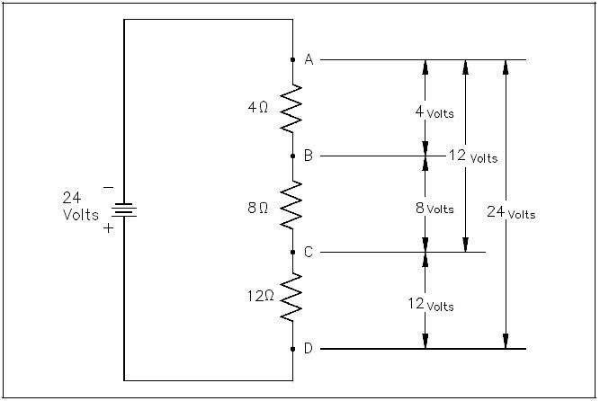
Voltage Divider
A voltage divider, or network, is used when it is necessary to obtain different values of voltage from a single energy source. A simple voltage divider is shown in Figure 12. In this circuit, 24 volts is applied to three resistors in series. The total resistance limits the current through the circuit to one ampere. Individual voltages are found as follows using equation (2-12).
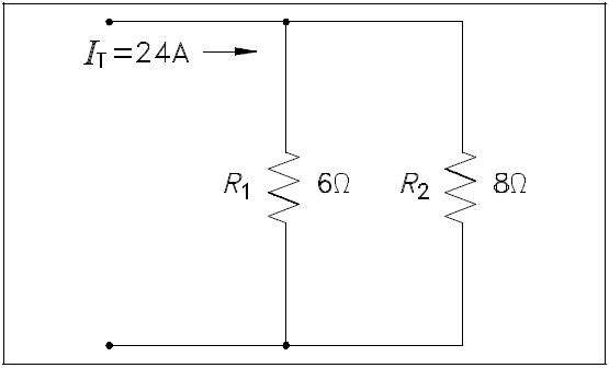
Current Division
Sometimes it is necessary to find the individual branch currents in a parallel circuit when only resistance and total current are known. When only two branches are involved, the current in one branch will be some fraction of IT. The resistance in each circuit can be used to divide the total current into fractional currents in each branch. This process is known as current division.
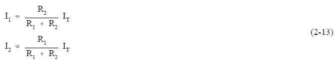
Note that the equation for each branch current has the opposite R in the numerator. This is because each branch current is inversely proportional to the branch resistance.
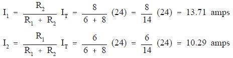
Example: Find branch current for I1 and I2 for the circuit shown in Figure 13.
Solution:
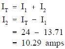
Since I1 and IT were known, we could have also simply subtracted I1 from IT to find I2:
DC Circuit Analysis
All of the rules governing DC circuits that have been discussed so far can now be applied to analyze complex DC circuits. To apply these rules effectively, loop equations, node equations, and equivalent resistances must be used.
Loop Equations
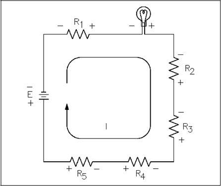
As we have already learned, Kirchhoffs Laws provide a practical means to solve for unknowns in a circuit. Kirchhoffs current law states that at any junction point in a circuit, the current arriving is equal to the current leaving. In a series circuit the current is the same at all points in that circuit. In parallel circuits, the total current is equal to the sum of the currents in each branch. Kirchhoffs voltage law states that the sum of all potential differences in a closed loop equals zero.
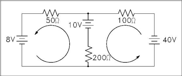
Using Kirchhoffs laws, it is possible to take a circuit with two loops and several power sources (Figure 14) and determine loop equations, solve loop currents, and solve individual element currents.
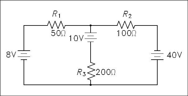
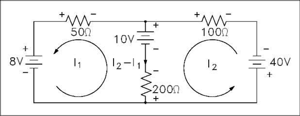
The first step is to draw an assumed direction of current flow (Figure 15). It does not matter whether the direction is correct. If it is wrong, the resulting value for current will be negative.
Second, mark the polarity of voltage across each component (Figure 16). It is necessary to choose a direction for current through the center leg, but it is not necessary to put in a new variable. It is simply I2 – I1.
Third, apply Kirchhoffs voltage law to loops one and two by picking a point in each loop and writing a loop equation of the voltage drops around the loop; then set the equation equal to zero.
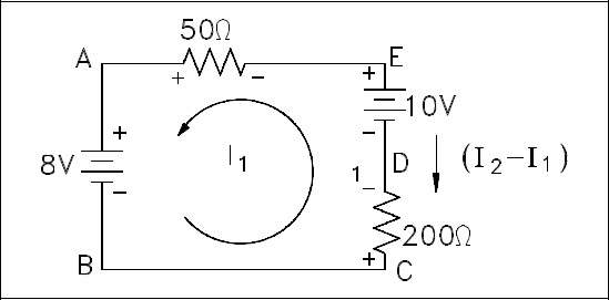
Figure 17 shows Loop one.
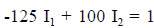
From Point A to Point B, there is an increase in voltage of 8 volts. From Point C to Point D, there is an increase in voltage of 200 (I2 – I1). From Point D to Point E, there is a decrease in voltage of 10 volts. From Point E to Point A, there is a voltage decrease of 50I1 volts. The result in equation form is illustrated in equation (2-16).

Using the same procedure for Loop 2 of Figure 16, the resulting equation is shown in equation (2-18).

Fourth, solve equations (2-17) and (2-18) simultaneously. First, rearrange and combine like terms in the equation for Loop 1.
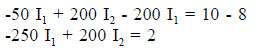
Divide both sides by two.
Rearrange and combine like terms in the Loop 2 equation.
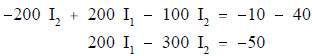
Multiplying the Loop 1 equation by 3, and add it to the Loop 2 equation.
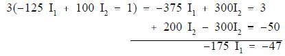
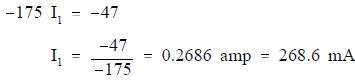
Solving for I1:
Solving for I2 using the Loop 1 equation:
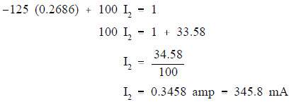
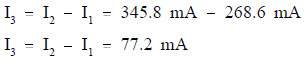
The current flow through R1 (50Ω) is I1. The current flow through R2(100Ω) is I2, and through R3(200Ω) is I2 – I1:
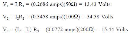
Fifth, apply Ohms Law to obtain the voltage drops across Resistors R1, R2, and R3:
Sixth, check the calculations by applying Kirchhoffs Laws:
Check 1: Apply Kirchhoffs voltage law to the larger outer loop (Figure 18).
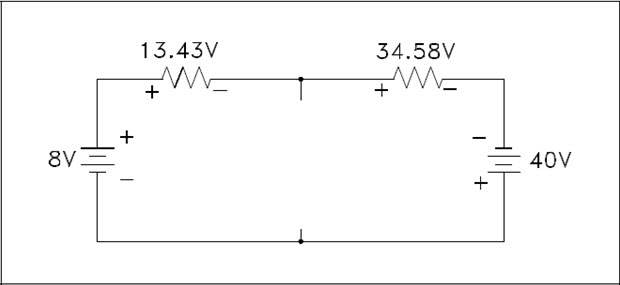
The sum of the voltage drops around the loop is essentially zero. (Not exactly zero due to rounding off.)
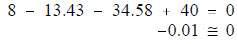
Therefore, the solution checks.
Check 2: Use Kirchhoffs current law at one of the junctions (Figure 19).
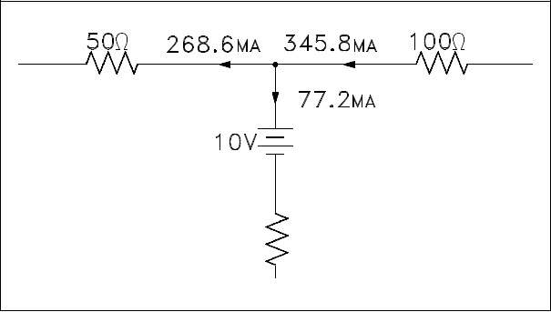
The sum of the currents out of the junction is:
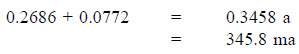
The current into the junction is 345.8 ma.
he current into the junction is equal to the current out of the junction. Therefore, the solution checks.
Node Equations
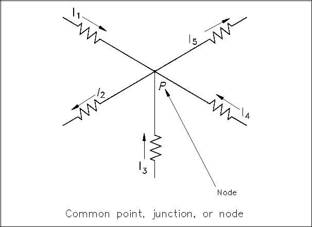
Kirchhoffs current law, as previously stated, says that at any junction point in a circuit the current arriving is equal to the current leaving. Let us consider five currents entering and leaving a junction shown as P (Figure 43). This junction is also considered a node.
Assume that all currents entering the node are positive, and all currents that leave the node are negative. Therefore, I1, I3, and I4 are positive, and I2 and I5 are negative. Kirchhoffs Law also states that the sum of all the currents meeting at the node is zero. For Figure 20, Equation (2-19) represents this law mathematically.

By solving node equations, we can calculate the unknown node voltages. To each node in a circuit we will assign a letter or number. In Figure 21, A, B, C, and N are nodes, and N and C are principal nodes. Principal nodes are those nodes with three or more connections. Node C will be our selected reference node. VAC is the voltage between Nodes A and C; VBC is the voltage between Nodes B and C; and VNC is the voltage between Nodes N and C. We have already determined that all node voltages have a reference node; therefore, we can substitute VA for VAC, VB for VBC, and VN for VNC.
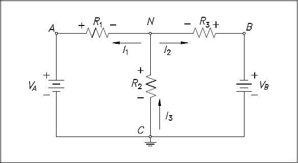
Assume that loop currents I1 and I2 leave Node N, and that I3 enters Node N (Figure 21).
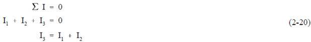
From Kirchhoffs current law:
Using Ohms Law and solving for the current through each resistor we obtain the following.
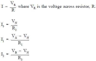
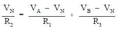
Substitute these equations for I1, I2, and I3 into Kirchhoffs current equation (2-20) yields the following.
The circuit shown in Figure 22 can be solved for voltages and currents by using the node-voltage analysis.
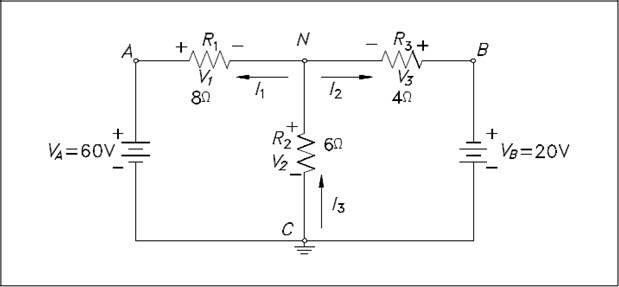
First, assume direction of current flow shown. Mark nodes A, B, C, and N, and mark the Analysis polarity across each resistor.
Second, using Kirchhoffs current law at Node N, solve for VN.
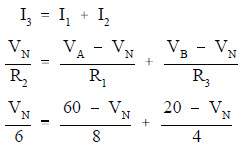
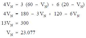
Clear the fraction so that we have a common denominator:
Third, find all voltage drops and currents.
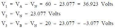
The negative value for V3 shows that the current flow through R3 is opposite that which was assumed and that the polarity across R3 is reversed.
The negative value for I3 shows that the current flow through R3 is opposite that which was assumed.
Series-Parallel Circuit Analysis
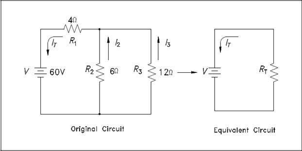
When solving for voltage, current, and resistance in a series-parallel circuit, follow the rules which apply to the series part of the circuit, and follow the rules which apply to the parallel part of the circuit. Solving these circuits can be simplified by reducing the circuit to a single equivalent resistance circuit, and redrawing the circuit in simplified form. The circuit is then called an equivalent circuit (Figure 23).
The easiest way to solve these types of circuits is to do it in steps.
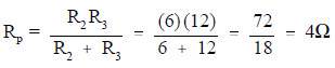
Step 1: Find the equivalent resistance of the parallel branch:
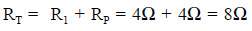
Step 2: Find the resistance of the equivalent series circuit:
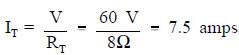
Step 3: Find total current (IT):
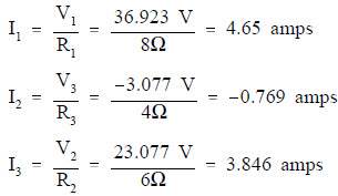
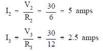
Step 4: Find I2 and I3. The voltage across R1 and R2 is equal to the applied voltage (V), minus the voltage drop across R1.

Then, I2 and I3 are calculated.
Y and Delta Network Calculation
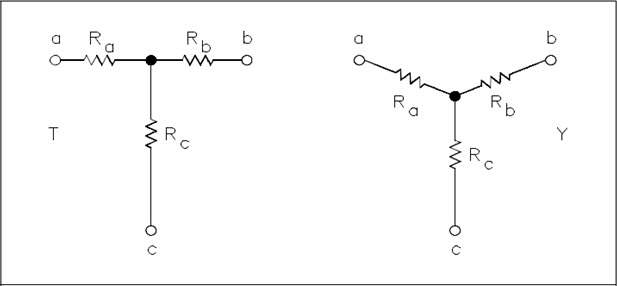
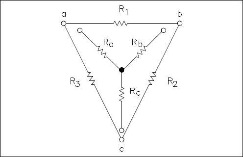
Because of its shape, the network shown in Figure 24 is called a T (tee) or Y (wye) network. These are different names for the same network.
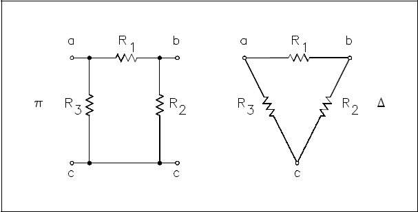
The network shown in Figure 48 is called π (pi) or Δ(delta) because the shapes resemble Greek letters π and Ω. These are different names for the same network.
In order to analyze the circuits, it may be helpful to convert Y to Δ, or Δ to Y, to simplify the solution. The formulas that will be used for these conversions are derived from Kirchhoffs laws. The resistances in these networks are shown in a three-terminal network. After we use the conversion formulas, one network is equivalent to the other because they have equivalent resistances across any one pair of terminals (Figure 26).
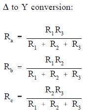
Rule 1: The resistance of any branch of a Y network is equal to the product of the two adjacent sides of a Δ network, divided by the sum of the three Δ resistances.
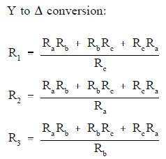
Rule 2: The resistance of any side of a Δ network is equal to the sum of the Y network resistance, multiplied in pairs, divided by the opposite branch of the Y network.
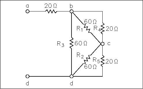
Let us consider a bridge circuit (Figure 27).
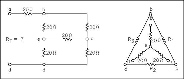
Find Rt at terminals a and d.
Step 1: Convert the Y network (b-e, e-c, e-d) to the equivalent Δ network.
- Using Rule 2:
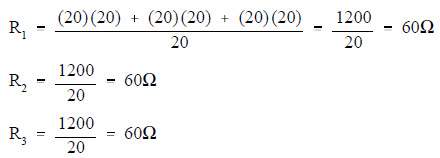
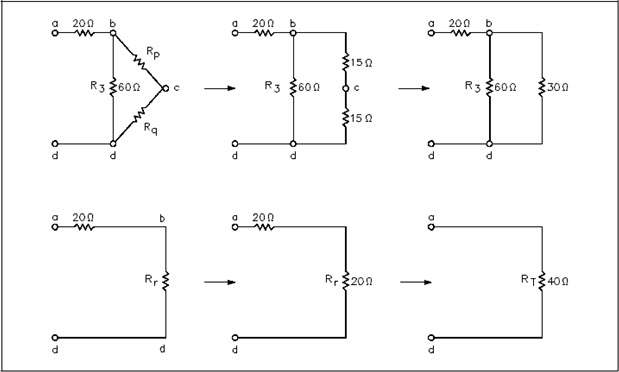
Step 2: Now, we can redraw the Y circuit as a Δ circuit and reconnect it to the original circuit (Figure 28):
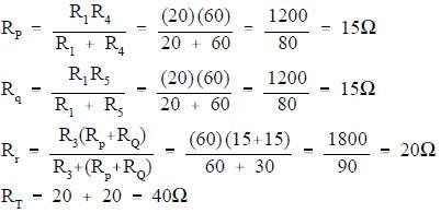
Step 3: Reduce and simplify the circuit. Note that the 20Ω and 60 Ω branches are in parallel in Figure 28. Refer to Figures 28 and 29 for redrawing the circuit in each step below.
DC Circuit Faults
Faults within a DC circuit will cause various effects, depending upon the nature of the fault. An understanding of the effects of these faults is necessary to fully understand DC circuit operation.
Open Circuit Series
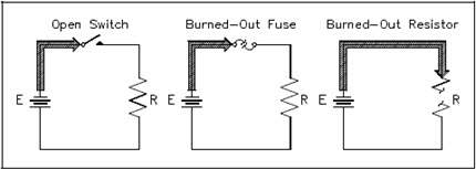
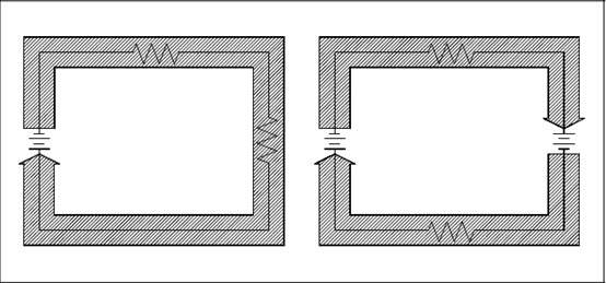
A circuit must have a “complete” path for current flow, that is, from the negative side to the positive side of a power source. A series circuit has only one path for current to flow. If this path is broken, no current flows, and the circuit becomes an open circuit (Figure 30).
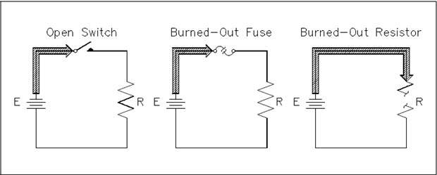
Circuits can be opened deliberately, such as by the use of a switch, or they may be opened by a defect, such as a broken wire or a burned-out resistor.
Since no current flows in an open series circuit, there are no voltage drops across the loads. No power is consumed by the loads, and total power consumed by the circuit is zero.
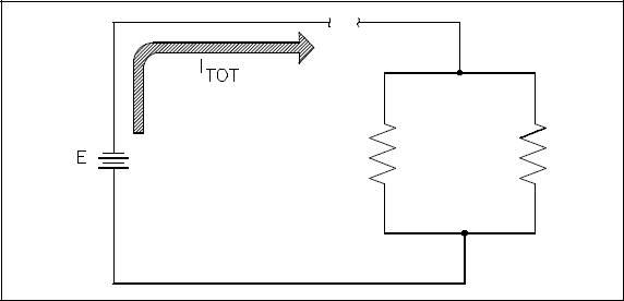
A parallel circuit has more than one path for current to flow. If one of the paths is opened, current will continue to flow as long as a complete path is provided by one or more of the remaining paths. It does not mean that you cannot stop current flow through a parallel circuit by opening it at one point; it means that the behavior of a parallel circuit depends on where the opening occurs (Figure 31).
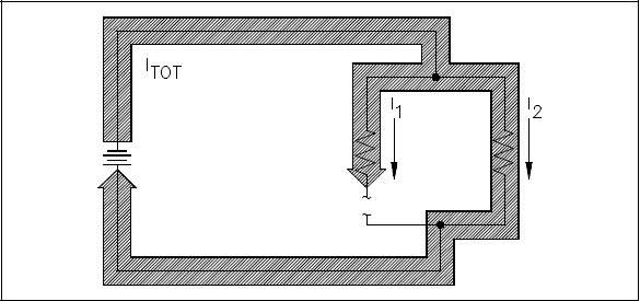
If a parallel circuit is opened at a point where only a branch current flows, then only that branch is open, and current continues to flow in the rest of the circuit (Figure 32).
Short Circuit Series
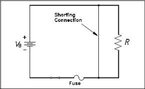
In a DC circuit, the only current limit is the circuit resistance. If there is no resistance in a circuit, or if the resistance suddenly becomes zero, a very large current will flow. This condition of very low resistance and high current flow is known as a “short circuit” (Figure 33).
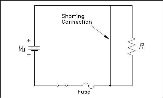
A short circuit is said to exist if the circuit resistance is so low that current increases to a point where damage can occur to circuit components. With an increase in circuit current flow, the terminal voltage of the energy source will decrease. This occurs due to the internal resistance of the energy source causing an increased voltage drop within the energy source. The increased
current flow resulting from a short circuit can damage power sources, burn insulation, and start fires. Fuses are provided in circuits to protect against short circuits.
Short Circuit Parallel
When a parallel circuit becomes short circuited, the same effect occurs as in a series circuit: there is a sudden and very large increase in circuit current (Figure 34).
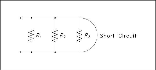
Parallel circuits are more likely than series circuits to develop damaging short circuits. This is because each load is connected directly across the power source. If any of the load becomes shorted, the resistance between the power source terminals is practically zero. If a series load becomes shorted, the resistance of the other loads keeps the circuit resistance from dropping to zero.
DC Circuit Terminology
Before operations with DC circuits can be studied, an understanding of the types of circuits and common circuit terminology associated with circuits is essential.
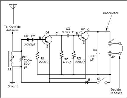
Schematic Diagram
Schematic diagrams are the standard means by which we communicate information in electrical and electronics circuits. On schematic diagrams, the component parts are represented by graphic symbols, some of which were presented earlier in Module 1. Because graphic symbols are small, it is possible to have diagrams in a compact form. The symbols and associated lines show how circuit components are connected and the relationship of those components with one another.
As an example, let us look at a schematic diagram of a two-transistor radio circuit (Figure 35). This diagram, from left to right, shows the components in the order they are used to convert radio waves into sound energy. By using this diagram it is possible to trace the operation of the circuit from beginning to end. Due to this important feature of schematic diagrams, they are widely used in construction, maintenance, and servicing of all types of electronic circuits.
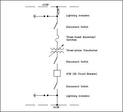
One-Line Diagram
The one-line, or single-line, diagram shows the components of a circuit by means of single lines and the appropriate graphic symbols. One-line diagrams show two or more conductors that are connected between components in the actual circuit. The one-line diagram shows all pertinent information about the sequence of the circuit, but does not give as much detail as a schematic diagram. Normally, the one-line diagram is used to show highly complex systems without showing the actual physical connections between components and individual conductors.
As an example, Figure 10 shows a typical one-line diagram of an electrical substation.
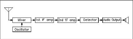
Block Diagram
A block diagram is used to show the relationship between component groups, or stages in a circuit. In block form, it shows the path through a circuit from input to output (Figure 37). The blocks are drawn in the form of squares or rectangles connected by single lines with arrowheads at the terminal end, showing the direction of the signal path from input to output. Normally, the necessary information to describe the stages of components is contained in the blocks.
Wiring Diagram
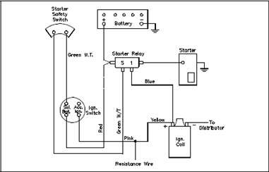
A wiring diagram is a very simple way to show wiring connections in an easy-to-follow manner. These types of diagrams are normally found with home appliances and automobile electrical systems (Figure 38). Wiring diagrams show the component parts in pictorial form, and the components are identified by name. Most wiring diagrams also show the relative location of component parts and color coding of conductors or leads.
Resistivity
Resistivity is defined as the measure of the resistance a material imposes on current flow. The resistance of a given length of conductor depends upon the resistivity of that material, the length of the conductor, and the cross-sectional area of the conductor, according to Equation (2-1).
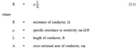
The resistivity ρ(rho) allows different materials to be compared for resistance, according to their nature, without regard to length or area. The higher the value of ρ, the higher the resistance.
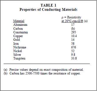
Table 1 gives resistivity values for metals having the standard wire size of one foot in length and a cross-sectional area of 1 cm.
Temperature Coefficient of Resistance
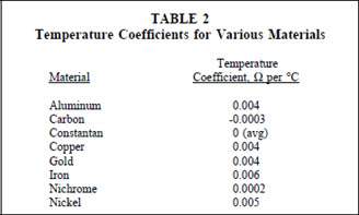
Temperature coefficient of resistance, α(alpha), is defined as the amount of change of the resistance of a material for a given change in temperature. A positive value of α indicates that R increases with temperature; a negative value of α indicates R decreases; and zero α indicates that R is constant. Typical values are listed in Table 2.
For a given material, α may vary with temperature; therefore, charts are often used to describe how resistance of a material varies with temperature.
An increase in resistance can be approximated from equation (2-2).
Electric Circuit
Each electrical circuit has at least four basic parts: (1) a source of electromotive force, (2) conductors, (3) load or loads, and (4) some means of control. In Figure 39, the source of EMF is the battery; the conductors are wires which connect the various component parts; the resistor is the load; and a switch is used as the circuit control device.
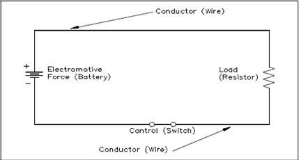
A closed circuit (Figure 39) is an uninterrupted, or unbroken, path for current from the source (EMF), through the load, and back to the source.
An pen circuit, or incomplete circuit, (Figure 40) exists if a break in the circuit occurs; this prevents a complete path for current flow.
A short circuit is a circuit which offers very little resistance to current flow and can cause dangerously high current flow through a circuit (Figure 41). Short circuits are usually caused by an inadvertent connection between two points in a circuit which offers little or no resistance to current flow. Shorting resistor R in Figure 15 will probably cause the fuse to blow.
Series Circuit
A series circuit is a circuit where there is only one path for current flow. In a series circuit (Figure 42), the current will be the same throughout the circuit. This means that the current flow through R1 is the same as the current flow through R2 and R3.
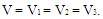
Parallel Circuit
Parallel circuits are those circuits which have two or more components connected across the same voltage source (Figure 43). Resistors R1, R2, and R3 are in parallel with each other and the source. Each parallel path is a branch with its own individual current. When the current leaves the source V, part I1 of IT will flow through R1; part I2 will flow through R2; and part I3 will flow through R3. Current through each branch can be different; however, voltage throughout the circuit will be equal.
Equivalent Resistance
In a parallel circuit, the total resistance of the resistors in parallel is referred to as equivalent resistance. This can be described as the total circuit resistance as seen by the voltage source. In all cases, the equivalent resistance will be less than any of the individual parallel circuit resistors. Using Ohms Law, equivalent resistance (REQ) can be found by dividing the source voltage (V) by the total circuit current (IT), as shown in Figure 43.

DC Sources
When most people think of DC, they usually think of batteries. In addition to batteries, however, there are other devices that produce DC which are frequently used in modern technology.
Batteries
A battery consists of two or more chemical cells connected in series. The combination of materials within a battery is used for the purpose of converting chemical energy into electrical energy. To understand how a battery works, we must first discuss the chemical cell.
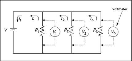
The chemical cell is composed of two electrodes made of different types of metal or metallic compounds which are immersed in an electrolyte solution. The chemical actions which result are complicated, and they vary with the type of material used in cell construction. Some knowledge of the basic action of a simple cell will be helpful in understanding the operation of a chemical cell in general.
In the cell, electrolyte ionizes to produce positive and negative ions (Figure 44, Part A). Simultaneously, chemical action causes the atoms within one of the electrodes to ionize.
Due to this action, electrons are deposited on the electrode, and positive ions from the electrode pass into the electrolyte solution (Part B). This causes a negative charge on the electrode and leaves a positive charge in the area near the electrode (Part C).
The positive ions, which were produced by ionization of the electrolyte, are repelled to the other electrode. At this electrode, these ions will combine with the electrons. Because this action causes removal of electrons from the electrode, it becomes positively charged.
DC Generator
A simple DC generator consists of an armature coil with a single turn of wire. The armature coil cuts across the magnetic field to produce a voltage output. As long as a complete path is present, current will flow through the circuit in the direction shown by the arrows in Figure 2. In this coil position, commutator segment 1 contacts with brush 1, while commutator segment 2 is in contact with brush 2.
Rotating the armature one-half turn in the clockwise direction causes the contacts between the commutator segments to be reversed. Now segment 1 is contacted by brush 2, and segment 2 is in contact with brush 1.
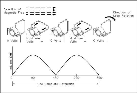
Due to this commutator action, that side of the armature coil which is in contact with either of the brushes is always cutting the magnetic field in the same direction. Brushes 1 and 2 have a constant polarity, and pulsating DC is delivered to the load circuit.
Thermocouples
A thermocouple is a device used to convert heat energy into a voltage output. The thermocouple consists of two different types of metal joined at a junction (Figure 46).
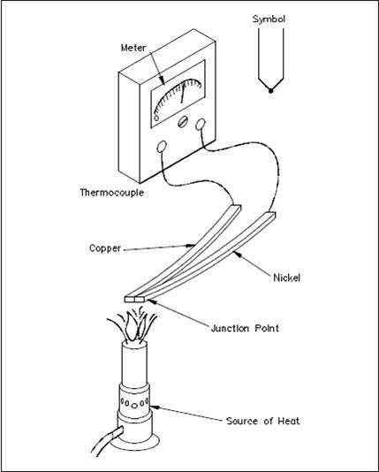
As the junction is heated, the electrons in one of the metals gain enough energy to become free electrons. The free electrons will then migrate across the junction and into the other metal. This displacement of electrons produces a voltage across the terminals of the thermocouple. The combinations used in the makeup of a thermocouple include: iron and constantan; copper and constantan; antimony and bismuth; and chromel and alumel.
Thermocouples are normally used to measure temperature. The voltage produced causes a current to flow through a meter, which is calibrated to indicate temperature.
Rectifiers
Most electrical power generating stations produce alternating current. The major reason for generating AC is that it can be transferred over long distances with fewer losses than DC; however, many of the devices which are used today operate only, or more efficiently, with DC. For example, transistors, electron tubes, and certain electronic control devices require DC for operation. If we are to operate these devices from ordinary AC outlet receptacles, they must be equipped with rectifier units to convert AC to DC. In order to accomplish this conversion, we use diodes in rectifier circuits. The purpose of a rectifier circuit is to convert AC power to DC.
The most common type of solid state diode rectifier is made of silicon. The diode acts as a gate, which allows current to pass in one direction and blocks current in the other direction. The polarity of the applied voltage determines if the diode will conduct. The two polarities are known as forward bias and reverse bias.
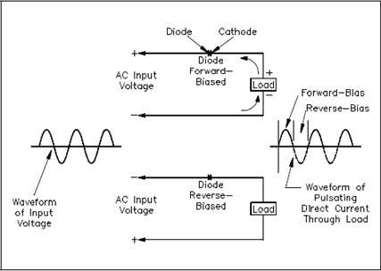
Forward Bias
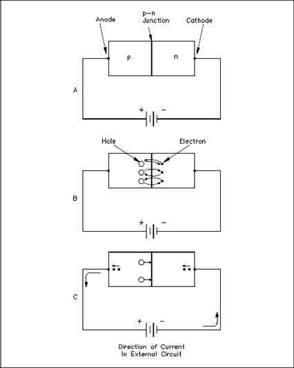
A diode is forward biased when the positive terminal of a voltage source is connected to its anode, and the negative terminal is connected to the cathode (Figure 47A). The power sources positive side will tend to repel the holes in the p-type material toward the p-n junction by the negative side. A hole is a vacancy in the electron structure of a material. Holes behave as positive charges. As the holes and the electrons reach the p-n junction, some of them break through it (Figure 47B). Holes combine with electrons in the n-type material, and electrons combine with holes in the p-type material.
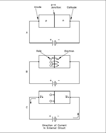
When a hole combines with an electron, or an electron combines with a hole near the p-n junction, an electron from an electron-pair bond in the p-type material breaks its bond and enters the positive side of the source. Simultaneously, an electron from the negative side of the source enters the n-type material (Figure 47C). This produces a flow of electrons in the circuit.
Reverse Bias
Reverse biasing occurs when the diodes anode is connected to the negative side of the source, and the cathode is connected to the positive side of the source (Figure 48A). Holes within the p-type material are attracted toward the negative terminal, and the electrons in the n-type material are attracted to the positive terminal (Figure 48B). This prevents the combination of electrons and holes near the p-n junction, and therefore causes a high resistance to current flow. This resistance prevents current flow through the circuit.
Half-Wave Rectifier Circuit
When a diode is connected to a source of alternating voltage, it will be alternately forward-biased, and then reverse-biased, during each cycle of the AC sine-wave. When a single diode is used in a rectifier circuit, current will flow through the circuit only during one-half of the input voltage cycle (Figure 50). For this reason, this rectifier circuit is called a half-wave rectifier. The output of a half-wave rectifier circuit is pulsating DC.
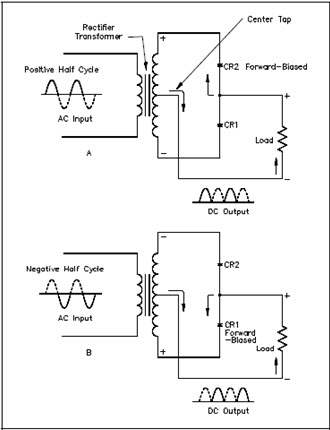
Full-Wave Rectifier Circuit
A full-wave rectifier circuit is a circuit that rectifies the entire cycle of the AC sine-wave. A basic full-wave rectifier uses two diodes. The action of these diodes during each half cycle is shown in Figure 51.
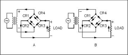
Another type of full-wave rectifier circuit is the full-wave bridge rectifier. This circuit utilizes four diodes. These diodes actions during each half cycle of the applied AC input voltage are shown in Figure 52. The output of this circuit then becomes a pulsating DC, with all of the waves of the input AC being transferred. The output looks identical to that obtained from a full-wave rectifier (Figure 52).
Kirchhoff’s Laws
Kirchhoffs two laws reveal a unique relationship between current, voltage, and resistance in electrical circuits that is vital to performing and understanding electrical circuit analysis.
In all of the circuits examined so far, Ohms Law described the relationship between current, voltage, and resistance. These circuits have been relatively simple in nature. Many circuits are extremely complex and cannot be solved with Ohms Law. These circuits have many power sources and branches which would make the use of Ohms Law impractical or impossible.
Through experimentation in 1857 the German physicist Gustav Kirchhoff developed methods to solve complex circuits. Kirchhoff developed two conclusions, known today as Kirchhoffs Laws.
Law 1: The sum of the voltage drops around a closed loop is equal to the sum of the voltage sources of that loop (Kirchhoffs Voltage Law).
Law 2: The current arriving at any junction point in a circuit is equal to the current leaving that junction (Kirchhoffs Current Law).
Kirchhoffs two laws may seem obvious based on what we already know about circuit theory. Even though they may seem very simple, they are powerful tools in solving complex and difficult circuits.
Kirchhoffs laws can be related to conservation of energy and charge if we look at a circuit with one load and source. Since all of the power provided from the source is consumed by the load, energy and charge are conserved. Since voltage and current can be related to energy and charge, then Kirchhoffs laws are only restating the laws governing energy and charge conservation.
The mathematics involved becomes more difficult as the circuits become more complex. Therefore, the discussion here will be limited to solving only relatively simple circuits.
Kirchhoffs Voltage Law
Kirchhoffs first law is also known as his “voltage law.” The voltage law gives the relationship between the “voltage drops” around any closed loop in a circuit, and the voltage sources in that loop. The total of these two quantities is always equal. In equation form:
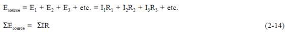
where the symbol Σ (the Greek letter sigma) means “the sum of.”
Kirchhoffs voltage law can be applied only to closed loops (Figure 53). A closed loop must meet two conditions:
- It must have one or more voltage sources.
- It must have a complete path for current flow from any point, around the loop, and back to that point.
You will remember that in a simple series circuit, the sum of the voltage drops around the circuit is equal to the applied voltage. Actually, this is Kirchhoffs voltage law applied to the simplest case, that is, where there is only one loop and one voltage source.
Applying Kirchhoffs Voltage Law
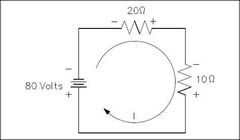
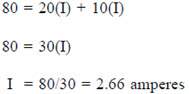
For a simple series circuit, Kirchhoffs voltage law corresponds to Ohms Law. To find the current in a circuit (Figure 54) by using Kirchhoffs voltage law, use equation (2-15).

In the problem above, the direction of current flow was known before solving the problem. When there is more than one voltage source, the direction of current flow may or may not be known. In such a case, a direction of current flow must be assumed in the beginning of the problem. All the sources that would aid the current in the assumed direction of current flow are then positive, and all that would oppose current flow are negative. If the assumed direction is correct, the answer will be positive. The answer would be negative if the direction assumed was wrong. In any case, the correct magnitude will be attained.
For example, what is the current flow in Figure 55? Assume that the current is flowing in the direction shown.
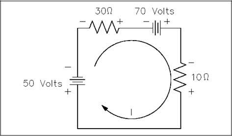
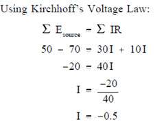
The result is negative. The current is actually 0.5 ampere in the opposite direction to that of the assumed direction.
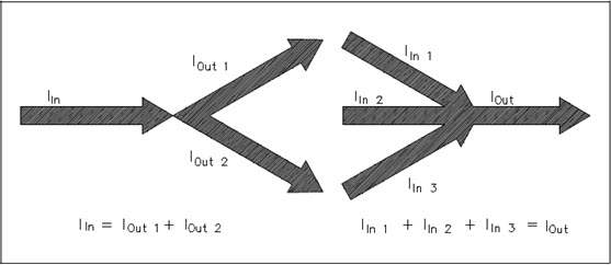
Kirchhoffs Current Law
Kirchhoffs second law is called his current law and states: “At any junction point in a circuit, the current arriving is equal to the current leaving.” Thus, if 15 amperes of current arrives at a junction that has two paths leading away from it, 15 amperes will divide among the two branches, but a total of 15 amperes must leave the junction. We are already familiar with Kirchhoffs current law from parallel circuits, that is, the sum of the branch currents is equal to the total current entering the branches, as well as the total current leaving the branches (Figure 56).
In equation form, Kirchhoffs current law may be expressed:
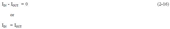
Normally Kirchhoffs current law is not used by itself, but with the voltage law, in solving a problem.
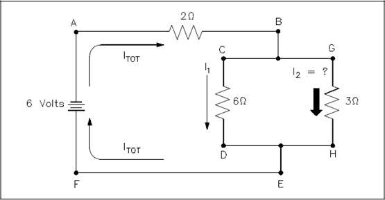
Example: Find I2 in the circuit shown in Figure 36 using Kirchhoffs voltage and current laws.
Solution:
First, apply Kirchhoffs voltage law to both loops.
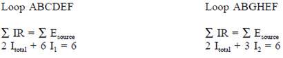
Since Kirchhoffs current law states Itotal = I1 + I2, substitute (I1 + I2) in the place of Itotal in both loop equations and simplify.
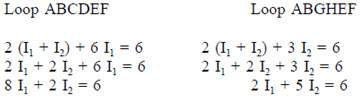
We now have two equations and two unknowns and must eliminate I1 to find I2. One way is to multiply Loop ABGHEF equation by four, and subtract Loop ABCDEF equation from the result.
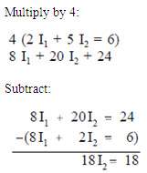
Now we have an equation with only I2, which is the current we are looking for.
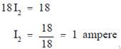
This circuit could have been solved simply by using Ohms Law, but we used Kirchhoffs Laws to show the techniques used in solving complex circuits when Ohms Law cannot be used.
Voltage Polarity and Current Direction
Before introducing the laws associated with complex DC circuit analysis, the importance of voltage polarity and current direction must be understood. This chapter will introduce the polarities and current direction associated with DC circuits.
Conventional and Electron Flow
The direction of electron flow is from a point of negative potential to a point of positive potential. The direction of positive charges, or holes, is in the opposite direction of electron flow. This flow of positive charges is known as conventional flow. All of the electrical effects of electron flow from negative to positive, or from a high potential to a lower potential, are the same as those that would be created by flow of positive charges in the opposite direction; therefore, it is important to realize that both conventions are in use, and they are essentially equivalent. In this manual, the electron flow convention is used.
Polarities
All voltages and currents have polarity as well as magnitude. In a series circuit, there is only one current, and its polarity is from the negative battery terminal through the rest of the circuit to the positive battery terminal. Voltage drops across loads also have polarities. The easiest way to find these polarities is to use the direction of the electron current as a basis. Then, where the electron current enters the load, the voltage is negative (Figure 31). This holds true regardless of the number or type of loads in the circuit. The drop across the load is opposite to that of the source. The voltage drops oppose the source voltage and reduce it for the other loads. This is because each load uses energy, leaving less energy for other loads.