This article begins with a review of the design of the heat recovery steam generator (HRSG), its flow paths, components, and subsystems. HRSG operation including startup, combined cycle plant startup, filling and flushing, and removing the HRSG from service were also reviewed.
We also describe the overall HRSG operating philosophy, details of special loops within the HRSG control philosophy, and a brief description of the installed instruments. Next, we describe the duct burner system that is used to increase steam production. In the final section, we review the selective catalytic reduction (SCR) system, its components, and operation.
HRSG Function and Design
As stated in Combine Cycle Theory, the combined cycle setup is a combination of a simple cycle gas turbine (Brayton cycle) and a steam power cycle (Rankine cycle). The Brayton cycle consists of the compressor, combustor, and combustion turbine.
HRSG Function
The exhaust gas from the combustion turbine becomes the heat source for the Rankine cycle portion of the combined cycle. Steam is generated in the heat recovery steam generator (HRSG). The HRSG recovers the waste heat available in the combustion turbine exhaust gas. The recovered heat is used to generate steam at high pressure and high temperature, and the steam is then used to generate power in the steam turbine/generator.
The HRSG is basically a heat exchanger composed of a series of preheaters (economizers), evaporator, reheaters, and superheaters. The HRSG also has supplemental firing in the duct that raises gas temperature and mass flow.
This section is intended to provide turbine operators with a basic understanding of heat recovery steam generator (HRSG) design and operation. The power generation block of the facility produces electrical power in two separate islands:
- The first island within the combined-cycle power block is the combustion turbine (CT) generator set.
- The second island is the HRSG steam turbine generator set.
The HRSG absorbs heat energy from the exhaust gas stream of the combustion turbine. The absorbed heat energy is converted to thermal energy as high temperature and pressure steam. The high-pressure steam is then used in a steam turbine generator set to produce rotational mechanical energy. The shaft of the steam turbine in connected to an electrical generator that then produces electrical power.
The waste heat is recovered from the combustion turbine exhaust gas stream through absorption by the HRSG. The exhaust gas stream is a large mass flow with temperature of up to 1,150F.
Most large HRSGs can be classified as a double-wide, triple-pressure level with reheat, supplementary fired unit of natural circulation design, installed behind a natural gas fired combustion turbine.
The steam generated by the HRSG is supplied to the steam turbine that drives the electrical generator system.
HRSG Design
The function of the combined cycle heat recovery steam generator (HRSG) system is to provide a method to extract sensible heat from the combustion turbine (CT) exhaust gas stream.
The heat is converted into usable steam by the heat transfer surfaces within the HRSG. The usable steam is generated in three separate and different pressure levels for use in a steam turbine (ST) generator set and for power augmentation of the CT.
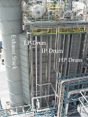
The pressure levels and their associated components are (”’Figure 1”’):
- High pressure (HP)
- Intermediate pressure (IP)
- Low pressure (LP)
- Reheat (RH)
- Feedwater preheater (FWPH)
All generated steam from the HP, RH, and LP systems is supplied to the steam turbine, except for some LP steam used for deaeration, The IP steam is mixed with the cold RH return loop prior to being admitted to the steam turbine.
Typical heat recovery steam generator circuits have four major components (”’Figure 2”’):
- Superheaters
- Evaporators
- Economizers
- Drum
Note: Remember the memory tool “SEED.”
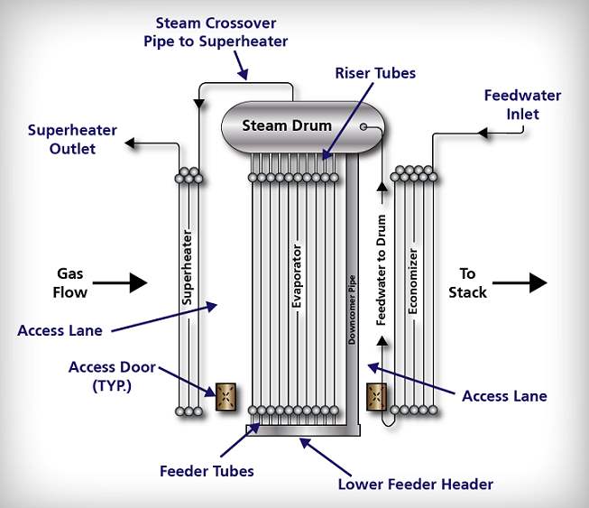
Since we are operating a triple-pressure system of HP, IP, and LP, we have these components for each associated pressure. These components (with the exception of the drum) are arranged in series in the gas flow path within the HRSG. Essentially, this means that the heat transfer boiler circuits are not in parallel with one another with respect to CT exhaust gas flow. The gas, after having been used to heat the water/steam in the HRSG is released to the environment through a stack.
HRSG Boiling
Boiling occurs in the evaporator of a typical steam generator circuit (”’Figure 3”’). This process changes the phase of water from liquid to vapor or steam. The steam is generated at the saturation temperature associated with the operating pressure.
When water is heated in an evaporator section and steam is generated, an increase in evaporator section pressure occurs. As the pressure increases, the temperature of the boiler water rises. Recall, the temperature at which boiling occurs for any given pressure is constant and is called the ”saturation temperature”. Therefore, the temperature of the water and the steam are equal since both are “saturated” with energy just in a different phase.
Two distinct types of boiler regimes have been observed. These regimes are referred to as ”’nucleate”’ and ”’film boiling”’.
- Nucleate boiling is characterized by the formation and release of steam bubbles from the solid/liquid wetted tube wall interface.
- Film boiling occurs when a steam film covers the tube wall.
Heat transferred from the tube wall surface to the fluid in the tube requires a temperature gradient or differential. The magnitude of the gradient depends primarily on the degree of nucleate boiling that is occurring. Operating pressure, tube metal material, and surface condition of the tube wall surface are secondary considerations in the determination of boiling regime occurring.
Sub-critical pressure HRSG evaporator design criteria is governed by avoiding departure from nucleate boiling (DNB). This design criteria ensures that water maintains the interior tube wall surfaces wet (and therefore cool) and the resulting temperature differential remains low. At the onset of DNB, the rate of bubble formation exceeds the rising rate. Dissolved solids or suspended solids, will begin to concentrate. The presence of concentrated corrosives will compromise the thin film of magnetic iron compounds, which results in a loss of tube wall metal.
If fully developed DNB occurs, a stable film or blanket of steam will form. Corrosives then concentrate at the edges of this blanket, causing metal loss at the perimeter. The metal at the interior of the blanket is left relatively intact. DNB prevention usually requires the elimination of hotspots, achieved by controlling the boilers operating parameters. Hotspots are caused by excessively increasing heat input, gas channeling, circulation failures, excessive blowdown, etc.
HRSG Natural Circulation
Natural circulation minimizes the potential for evaporator tube overheating. This is achieved by providing a continuous supply of water to the entrance of the steam-generating tubes.

Natural circulation, as previously discussed, is based on the difference in density between water and steam. As heat energy is absorbed, a steam/water mixture is generated in the tubes. The steam/water mixture in the tubes is less dense than the water in the downcomers and rises up to the steam drum. The circulation process continues with a steam/water mixture being generated in the tubes and being replaced with heavier water from the downcomers.
As more heat is added to the boiler tubes, the steam quality of the fluid increases. Since the density difference becomes greater, more “pumping” power is available from the natural circulation effect. Up to a point, circulation naturally will increase with increased heat input and provide more flow to keep the boiler tubes cooled as more steam is generated. Beyond a certain level, friction in the tubes overcomes the difference in density, and circulation is reduced with additional heat input.
Natural circulation also provides an additional benefit. It partially compensates for normal imbalances in the heat input to the boiler tubes. If one tube receives more heat than adjacent tubes, it will generate more cooling flow. If the heat imbalance becomes too great, flow will be reduced, and the tube metal will overheat.
A steam/water mixture exits evaporator tubes at about the same temperature it enters the tubes. Natural circulation ensures that hotspots on steam generating tubes do not form. Tube metal temperatures are kept near the operating saturation temperature, which provides for a long life of the steam generator.
Flow Paths
The HRSG has two flow paths: gas-side and water-side.
The gas-side flow path starts at the combustion turbine outlet and proceeds through the HRSG to its associated outlet stack.
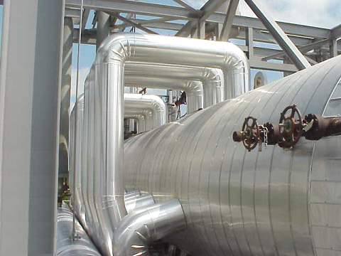
The water-side flow path starts at the condenser, proceeds to the condensate and feedwater pumps, and then to the associated steam drum where the water becomes steam and is sent to the steam turbine (”’Figure 4”’).
Gas-Side Flow Path
The gas flow begins at the discharge end of the combustion turbine, flows in a single pass through various modules in the HRSG and escapes to atmosphere through the stack. The CT exhaust gas is directed to the HRSG modules by its inlet duct. The gas flows across the duct burner located typically between the HP Superheater sections.
Water-Side Flow Path
The condensate off the steam turbine condenser enters the last section (FW preheater) of the HRSG in relationship to the gas flow path. The heated feedwater enters the LP drum and mixes with the water in the drum. The water leaves the drum via the downcomers and enters the LP evaporator.
The LP evaporator is composed of single pass evaporation modules. The LP evaporator generates steam that exits the evaporator tubes and enters the drum as a steam/water mixture through the riser tubes. Steam/water separation occurs in the steam drum. A continuous recirculation of water and steam/water mixture occurs producing saturated steam. The steam exits the LP steam drum and, after superheating, admitted to the LP section of the steam turbine.
The feedwater pumps take suction off the LP drum and discharge to the feedwater system through the IP economizer.
The water flow for the IP economizer flows across the gas flow from left to right. The IP feedwater/drum level control valve controls the water to the IP economizer as required by the drum. The feedwater enters the IP steam drum and mixes with the water in the drum. The water leaves the drum via the downcomers and enters the IP evaporator. The IP evaporators generate steam, which exits the evaporator tubes and enters the drum as a steam/water mixture through the riser tubes. Steam/water separation occurs in the steam drum. A continuous recirculation of water and steam/water mixture occurs, producing saturated steam. The saturated steam exits the IP steam drum. Saturated steam leaving the IP drum is transferred to the superheater. The steam is superheated through the IPSH module. The IP superheated steam is mixed with cold reheat steam. ”Cold reheat steam” (CRH) is the name for the steam that is exhausted from the HP turbine.
The cold reheat steam, discharged from the outlet of the HP steam turbine, and the IP superheated steam are mixed and admitted to the reheat (RH) Module No.2 for further superheating.
The hot reheat steam from the reheater is fed to the intermediate steam turbine through a hot reheat (HRH) pipeline. ”Hot reheat” is the name of the steam once the HP exhaust steam is mixed with the superheated IP steam.
The feedwater enters the HP feedwater system and is pumped by the HP feed pump through the HP economizer. The HP feedwater then passes to the HP steam drum. The HP feedwater/drum level control valve controls the water to the HP economizer as required.
The feedwater enters the HP steam drum and mixes with the water in the drum. The water leaves the drum via the downcomers and enters the HP evaporator. The HP evaporator generates steam that exits the evaporator tubes and enters the drum as a steam/water mixture through the riser tubes. Steam/water separation occurs in the steam drum. A continuous recirculation of water and steam/water mixture occurs, producing saturated steam. The saturated steam exits the HP steam drum. Saturated steam leaving the HP drum is transferred to the superheater. The steam is superheated through the HPSH Modules. Superheated steam exiting the superheater module is collected in the HP superheater outlet header and passes through the HP superheater non-return and outlet stop valves. The superheated steam is then routed to the HP turbine.
HRSG Components
Economizer
The first major HRSG circuit component is the economizer. An economizers function is to increase water temperature to an “approach” temperature near the saturation temperature. Approach temperature is carefully chosen to ensure maximum heat energy absorption efficiency and operational flexibility.
Economizers are “once-through” heat exchangers. These components can be designed for ”steaming” or ”nonsteaming”. The selection of steaming versus nonsteaming economizers is based on operational consideration, water quality, heat absorption optimization, and boiler life. The economizers included in this HRSG are nonsteaming.
An economizer is referred to as a steaming economizer when steam production occurs in this section. The cause of steaming is a result of heat energy absorption beyond design limits. Typically, this occurs during episodes of high CT exhaust gas flow and low economizer water flow. A specific episode that illustrates this is during a cold startup, no steam is being generated; however, a large quantity of CT exhaust gas is passing through the HRSG.
Economizer sections are composed of extended or finned tube surface modules. The economizer section includes multipass, three-row modules with required drains and vents. These modules are arranged in a series/parallel configuration to reach the desired final water temperature and capacity. Water flow rate control through the economizer is achieved through the drum level control instruments.
Steam Drum
The HRSG is equipped with a high-, intermediate-, and low-pressure steam drums. The steam drums are steam/water separators, storage tanks, and water treatment sites for steam purity control.
Drum boilers operate in the area on the saturation curve. The steam/water mixture entering the drum from the riser tubes usually is 5-10% steam depending on the boiler load and pressure. Staying at low-quality levels protects the tubes from overheat failures due to the nature of the boiling process.
In the steam drum, saturated steam is separated from the steam/water mixture. The separated steam rises up through the drum as feedwater enters the drum from the economizer. The separated water from the steam/water mixture is then recirculated together with the feedwater to the heat absorbing evaporator tubes through the circulation loop. The steam/water separation is done through a combination of gravity and mechanical components.
Drum steam/water separation relies on proper maintenance of a distinct water level in the drum. This distinct water level is referred to as the normal water level (NWL). Maintaining NWL ensures a free, controlled surface for steam/water mixture separation and proper operation of the primary separation equipment. Drum level can fluctuate during load swings. The speed at which these fluctuations occur is a result of the CT exhaust gas flow rate varies during CT load shifts.
In the steam drums, the separation of steam from the steam/water mixture generated takes place in two steps. Primary centrifugal separation removes nearly all of the water from the mixture, so that in effect, no steam is recirculated to the boiler water. However, the steam may still contain some water and solid contaminants that must be removed or reduced in amount before the steam is sufficiently pure for use. This step is called ”secondary separation” or ”steam scrubbing”.
Primary steam separation is accomplished with cyclone steam separators. The cyclones, essentially cylindrical in form, are arranged internally along the length of the drum. The riser tube steam/water mixture enters the cyclone steam separator tangentially. Centrifugal force throws the more dense water to the outside of the cylinder where it forms a layer against the cylinder wall. The steam moves to the center of the cylinder and rises upward. The water flows down the cylinder wall by gravity and is discharged from the cyclone through an annulus located below the water level. The separated water returns to the boiler cycle virtually free of steam bubbles, thus providing a maximum available head for producing flow through natural circulation. The steam rising upward from the cyclones passes through the corrugated scrubbers at the top of the cylinder for secondary steam separation. Secondary separation is necessary to remove droplets that contain solids, which can pass through the primary steam separation elements.
The secondary scrubbers achieve further steam scrubbing of any trace amounts of water or contaminants in the steam. Located at the top of the steam drum, these corrugated plates provide a large surface that intercepts water particles as the steam weaves through the closely fitted plates. Steam velocity through the corrugated plate assembly is very low, so that re-entrainment of water is avoided. The collected water is drained from the bottom of the scrubber assembly to the water below. The drum is designed to act as a storage tank or reservoir, allowing the boiler to accommodate upsets in feed pump operation and to “smooth out” transient drum level excursions during load swings.
The steam drum acts as a contact vessel for internal boiler water treatment by chemicals. Continuous slowdown for reduction of solids concentration in the boiler water is an integral part of the chemical water treating process. Continuous slowdown has been included in the design, and the nominal slowdown rate is set at 1 % but can be adjusted based on water quality.
Each steam drum head includes an elliptical manway, providing access to drum internals and connections for the remote level indicators, level gauges, and other control instruments. Each steam drum also contains connections for pressure safety relief valves, vents, pressure indicators, nitrogen blankets, downcomers, riser pipes, continuous blowdown, chemical feeds, and other control instruments. Steam drums are furnished with vents as required by ASME Section I Boiler Code. The drum vents are used to vent air during boiler filling and venting noncondensable gas during cold starts.
Downcomers/Feeder Headers
The downcomer/feeder headers are important components within the natural circulation evaporator module loop. The downcomer conveys water from the steam drum to the feeder header. The feeder header receives the water from the downcomer and distributes water to the evaporator modules.
Downcomer inlets are equipped with vortex breakers that disrupt the swirling motion of the water flowing from the drum and into the downcomer. The downcomer inlets are also covered with a mesh screen to prevent accidental dropping of tools and other materials during inspection and maintenance. The feeder header also acts as a sediment trap that must be blown clear from the evaporator circuit. The feeder header also contains connections for chemical cleaning, drain lines, and intermittent blowoff.
Evaporator
Evaporator sections are where the boiling process or steam generation occurs. As heat energy is absorbed by water from the gas stream, the water temperature increases. When water reaches the boiling point or saturation temperature, some of the water evaporates or vaporizes to steam. The evaporator sections are single-pass, two- and three-row modules. The single pass is on the water side and is vertically up. The modules feed a steam/water mixture to the riser pipes. The modules are fed with water from the downcomer/feeder header assembly to replace the water exiting as a steam/water mixture.
Superheater
The last major component of a steam generator circuit is the superheater. The major function of a superheater is to increase steam temperature above saturation. High steam temperature minimizes the introduction of water as liquid to the steam turbine and improves steam cycle efficiency. The superheater absorbs heat energy from the CT exhaust gas and transfers this energy to the steam. The steam superheat energy level is measured as an increase in steam temperature beyond the steam temperature achieved in the evaporator section. The superheater sections typically have the highest metal temperatures in the HRSG. Superheater sections are composed of extended or finned tube surface modules. The high-pressure superheater modules are one-pass, two-row modules and are arranged in a series/parallel configuration to reach the desired final steam temperature and capacity.
Drainable superheaters are employed in the most HRSG designs to ensure that any liquid water accumulated in the lower module headers are removed during startup. The water may be there as a result of the filling process, or condensate formed during the purge of a “hot” or “warm” start.
Drainable superheaters allow the HRSG to startup following the CT exhaust gas flow ramp. The steam temperature generated during startup will be about the same temperature as the CT exhaust gas temperature as the steam flow is initially very low. This situation is caused by the high heating surface area to steam flow that exists during this transient condition. The open vents and drains ensure that adequate steam flow is available to cool superheater metal temperature. Superheated steam exits the high-pressure system through an outlet stop-check and motorized gate-stop valves. The outlet stop-check valve may not operate properly at low steam flows.
HRSG Systems
The HRSG is composed of the following five systems:
- Setting
- Duct burner
- Pressure parts
- SCR
- Instruments
Setting System
The setting system provides CT exhaust gas containment ductwork, encasement of the various heat recovery module units, access to equipment via platforms, ladder and stair systems, duct expansion joints, casing penetration seals, and the exhaust stack. The HRSG setting includes ductwork transitions for connections with the CT exhaust and the HRSG module boxes.
Ductwork
The ductwork sections are typically fabricated of carbon steel, specification ASTM A-36 or SA- 283 grade C carbon steel plate, and reinforced with A-36 carbon steel exterior structural steel to withstand the specified internal design pressure, wind load, and seismic load. Construction is all welded gas-tight to prevent external gas leakage including both shop and field joints.
The ductwork sections are internally lined with multiple layers of thick ceramic fiber insulation covered with stainless steel liner panels to reduce heat transfer of CT gases to exterior surfaces. This ductwork design is referred to as a ”cold casing” design. The advantages to the design are that expansion of the ductwork is minimized and the elimination of the insulation exposure to the ambient environment. Liner panels are made of stainless steel material.
Liner panels are attached to the ductwork with stainless steel studs welded to the inside surfaces of the carbon steel ducts. The liner panels are designed to provide for differential expansion between the hot interior of the pressure containment ducts and casing of the modular units. Expansion joints are provided between the gas outlet of the HRSG and stack.
Access doors are provided for entry into various sections of the HRSG, including the inlet duct and stack. The access doors are equipped with access platforms and are located on both sides of the unit. Insulation is provided for the inside of the doors where elevated temperatures are encountered.
Pressure Parts
HRSG Casing
The HRSG casing is typically carbon steel, specification A-36 or SA-283, and is reinforced with A-36 carbon steel structural steel on the exterior to withstand the specified internal design pressure wind load and seismic load. Construction is all welded gas-tight to prevent external gas leakage, including both shop and field joints. The HRSG module box assemblies are internally lined partially with multiple layers of ceramic fiber insulation covered with liner panels to reduce heat transfer of CT gases to exterior surfaces. Stainless steel liner panels are usually attached to the ductwork with stainless steel studs welded to the inside surfaces of the carbon steel casing. The liner panels are designed to provide for differential expansion between the hot interior of the pressure containment ducts and casing of the modular units.
Outlet Stack
The stack is typically an all-welded, free-standing, self-supported, uninsulated, A-36 carbon steel structure. The stack is connected to the outlet of the HRSG with uninsulated ductwork or breaching and an expansion joint. The stack is usually equipped with EPA test ports. All of these items are accessible by the ladder and platform system supplied.
Expansion Joints
The HRSG is equipped with one fabric expansion joint between the outlet of the HRSG and the stack breaching. The fabric belt is clamped to the frame by a series of bolts and bars that provide the sealing pressure to the edge of fabric around the entire periphery of the belt.
Casing Penetrations
Piping that penetrates the casing is sealed by a bellows-type metallic expansion joint. Each bellows has been specifically designed and selected for the predicted thermal differential movements between the pipe and the casing.
High-Pressure Steam Generator
The HPSG is composed of an economizer (HP ECON), evaporator (HP EVAP), and superheater (HP SH). The HPSG flow path is from the economizer to the steam drum/evaporator and finally to the superheater. The sections are located strategically in the exhaust gas stream according to the declining temperature of the exhaust gas and the increasing temperatures of the heated feedwater, thus providing maximum energy recovery from the CT exhaust. The location of these heat transfer surfaces may be found on the right side setting elevation drawing.
The HPSG is equipped with a system of three safety relief valves; typically, two are mounted vertically on top of the drum, and one is mounted vertically on the HP main steam header. All PSVs are closed during normal operation; however, in an overpressure situation, the HP superheater PSV will lift first. If the pressure continues to build, the HP drum PSVs will lift (lowest pressure setting first). The three PSVs are designed to relieve 100% of the total HP steam-generating capacity.
High-Pressure Economizer
Each module is multipass on the water side and single-pass on the gas side. This is accomplished by internal baffles in the upper and lower module headers.
The HPEC receives feedwater from the feed pumps (provided by others) and absorbs heat from the CT exhaust gas, lowering the CT exhaust gas temperature and raising the water temperature to near saturation prior to entering the high-pressure steam drum.
High-Pressure Evaporator
In the HP EVAP section, the phase change between water and steam occurs. This phase change occurs due to the convective heat transfer or energy exchange between the CT exhaust gas stream and the water in the HP EVAP modules. The HP EVAP modules are all single-pass with no upper and lower header internal baffles. Steam/water mixture flows in upward direction through the tubes and escapes to the steam drum via riser system. Water is fed to the modules from the two downcomer feeder header assemblies. This is referred to as a ”’natural circulation loop”’.
High-Pressure Steam Drum
The HP steam drum (”’Figure 5”’) receives the HP ECON outlet feedwater and distributes/ mixes it with the drum water. The drum water is fed to the bottom of the HP evaporator modules through the downcomers, feeder headers, and feeder tubes. As steam is generated, the steam/water mixture flows to the top of the evaporator modules and returns to the HP steam drum via the riser tubes, thus completing the natural circulation loop.
High-Pressure Superheater
Steam on the inside of the tubes is received from the high-pressure steam drum at saturated temperature and is heated to final steam temperature.
The HP superheater is equipped with an interstage attemperator. The attemperator control valve and spray nozzle assembly typically is located between HP SHTR 2 and HP SHTR 3. The attemperator is supplied for final steam temperature control. The spray attemperation process uses water as the cooling media. The spray water is directly fed to the attemperator from the HP feed pumps discharge line. Final steam temperature control is important for protection of the superheater and equipment served by the HRSG. The spray attemperation is designed to limit final steam temperature at HP superheater outlet to final design steam temperature.
Intermediate Pressure Steam Generator
The IPSG is composed of an economizer (IP ECON), evaporator (IP EVAP), and superheater (IP SH). The IP steam generator economizer forms a tube bank consisting typically of two rows. The IP EVAP consists of many rows and the IP SH consists of typically only two rows. The IPSG flow path is from the economizer to the steam drum/evaporator and finally to the superheater. The sections are located strategically in the exhaust gas stream according to the declining temperature of the exhaust gas and the increasing temperatures of the heated feedwater, thus providing maximum energy recovery from the CT exhaust.
The IPSG is equipped with a system of three safety relief valves; typically, two are mounted vertically on top of the drum, and one is mounted vertically on the IP main steam header. All PSVs are closed during normal operation; however, in an overpressure situation, the IP superheater PSV will lift first. If the pressure continues to build, the IP drum PSVs will lift (lowest pressure setting first). The three PSVs are designed to relieve 100% of the total IP steam-generating capacity.
Intermediate Pressure Economizer
Each module is multipass on the water side and single-pass on the gas side. This is accomplished by internal baffles in the upper and lower module headers. The IPEC receives feedwater from the feed pumps (provided by others) and absorbs heat from the CT exhaust gas, lowering the CT exhaust gas temperature and raising the water temperature to near saturation before entering the steam drum.
Intermediate Pressure Evaporator
In the IP EVAP section, the phase change between water and steam occurs. This phase change occurs due to the convective heat transfer or energy exchange between the CT exhaust gas stream and the water in the IP EVAP modules. The IP EVAP modules are all single-pass with no upper and lower header internal baffles. Steam/water mixture flows in upward direction through the tubes and escapes to the steam drum via riser system. Water is fed to the modules from the two downcomer feeder header assemblies. This is referred to as a ”natural circulation loop”.
Intermediate Pressure Steam Drum
The IP steam drum receives the IP ECON outlet feedwater and distributes/mixes it with the drum water. The drum water is fed to the bottom of the IP evaporator modules through the downcomers, feeder headers, and feeder tubes. As steam is generated, the steam/water mixture flows to the top of the evaporator modules and returns to the HP steam drum via the riser tubes, thus completing the natural circulation loop. The downcomer pipe inlets are equipped with Vortex breakers that disrupt the swirling motion of the waterflow from the drum and into the downcomer. The downcomers are also covered with a mesh screen to prevent the loss of materials during inspection and maintenance.
Intermediate Pressure Superheater
Steam on the inside of the tubes is received from the steam drum at saturated temperature and is heated to final steam temperature.
Reheater
Steam on the inside of the tubes is received from the cold reheat line at the HP steam turbine discharge. The cold reheat steam is superheated by the reheater to a final hot reheat steam temperature.
The RH is equipped with an interstage attemperator located prior to the final reheater module. The attemperator is supplied for final steam temperature control. The spray attemperation process uses water as the cooling media. The spray water is directly fed to the attemperator from the IP feed pumps discharge line. Final steam temperature control is important for protection of the reheater and equipment served by the HRSG.
Low-Pressure Steam Generator
The low-pressure steam generator includes an evaporator (LP EVAP) and a superheater (LPSH). The two are circuit components and are in-series interspersed within the HRSG setting. The LPSG flow path is from the LP ECON, to the steam drum/evaporator, and finally to the superheater. There are no intervening valves between the steam drum and the superheater surface. The location of these heat transfer surfaces may be found on the Vogt-NEM sectional right-side elevation drawing.
The LPSG is equipped with a system of three safety relief valves; typically, two are mounted vertically on top of the drum, and is one mounted vertically on the LP main steam header. All PSVs are closed during normal operation; however, in an overpressure situation, the LP superheater PSV will lift first. If the pressure continues to build, the LP drum PSVs will lift (lowest pressure setting first). The three PSVs are designed to relieve 100% of the total LP steam-generating capacity, including maximum pegging steam.
Low-Pressure Evaporator
The LP EVAP modules are all single-pass with no upper and lower header internal baffles. The modules are oriented in this direction to allow steam bubbles generated to escape via the riser tubes to the steam drum. Water is fed to the modules from the downcomer feeder header assemblies. This is referred to as a ”natural circulation loop”.
In the LP EVAP section, the phase change between water and steam or steam generation occurs. This phase change occurs due to the convective heat transfer or energy exchange between the gas turbine exhaust gas stream and the water in the LP EVAP tubes generating steam.
Low-Pressure Steam Drum
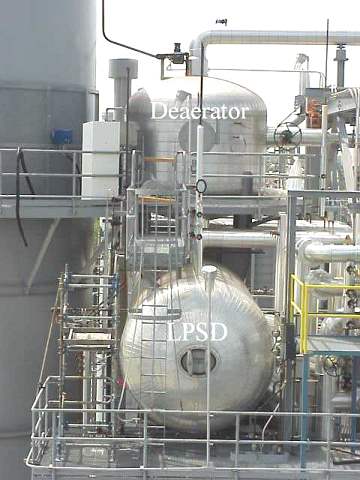
The LP steam drum (”’Figure 6”’) receives feedwater and mixes it with the drum water. The drum water is fed to the bottom of the LP evaporator modules through the downcomers, feeder headers, and feeder tubes. As steam is generated, the steam/water mixture flows to the top of the evaporator modules and returns to the LP steam drum via the riser tubes or riser collection header, thus completing the natural circulation loop. The drum can also used as a storage tank for an optional deaerator.
Low-Pressure Superheater
Steam on the inside of the tubes is received from the steam drum at saturated temperature and is heated to final steam temperature.
Feedwater Preheater
The modules have multiple passes on the water side. This is accomplished by internal baffles in the upper and lower headers.
The FW PHTR receives feedwater from the condensate pump system and absorbs heat from the gas turbine exhaust, lowering the gas temperature and raising the water temperature. The FW PHTR increases HRSG efficiency.
Startup
Combustion Turbine
The combustion turbine (CT) is the fastest-starting component of the combined cycle system. The CT is started by some auxiliary means (starting motor or self-started using the generator as a motor), and then fuel is introduced. The combustion of fuel generates power that increases the speed. The CT is coupled with the electrical generator to produce electrical power.
Heat Recovery Steam Generator
The HRSG does not have any moving parts, but it has thermal inertia, and rapid heating may result in high thermal stresses, which would affect the operating life of the HRSG. In a HRSG, the high-pressure drum is most vulnerable to buildup of thermal stresses if heating is done very rapidly. To preclude this possibility, the drum is heated in a controlled manner. The magnitude of the stress depends on the temperature difference which, in turn, depends on the material type thickness, operating pressure of the component, and the fatigue life cycles.
Controlling the pressure inside the drum can effectively control the temperature difference. If a certain temperature difference is close to the design limit, it can be controlled at that level by holding the pressure constant until the temperature difference decreases because of an increase in the component temperature due to conduction. The constant pressure or saturation temperature line on the drum heating chart indicates this.
Before an HRSG is put online, it is filled with water, and heat is applied. The cold metal takes some time to get heated, and time is required to soak the HRSG. The HRSG starts producing steam after a soaking period of a few minutes. If the steam is not released, then the pressure starts building up. The amount of steam produced and the increase in the pressure depend on the amount of heat supplied. More heat produces more steam, and pressure increases at a faster rate.
The drum pressure can be controlled either by relieving the generated steam or by controlling the heat input to the boiler.
Oftentimes, a combination of both means is used to accomplish the controlled heating of the HRSG. The steam is relieved by venting to the atmosphere or by sending it to a heat sink such as a condenser. Operating the CT at reduced load controls the heat input. A gas-side bypass system, which diverts part of the hot CT gasses to atmosphere, is sometimes used to control the heat input to the boiler. It is not necessary to run the CT at reduced load if a bypass system is provided.
HRSG Startup Without a Gas Bypass Damper
The CT and the HRSG are connected directly without a bypass damper if the power production is to be maximized and there is no requirement of simple cycle operation. In these systems, the HRSG receives heat whenever the CT is running. Thus, HRSG would produce steam whenever CT is in operation.
It is possible under certain circumstances to run the HRSG “dry,” or produce no steam, while the CT is operating. Usually, this requires additional constraints in the design and limitations on CT exhaust temperature. This means that CT cannot operate at full load for dry boiler operation.
An HRSG without a bypass damper can be started in different ways depending on the operating philosophy and auxiliary support provided. Initially, when the CT is started and is picking up speed, the hot gases, which have a temperature of about 700F, pass through the HRSG and heat the metal and the cold water in the tubes. The CT startup period until the CT attains the synchronous speed is thus utilized as a soaking in time for the HRSG.
If the plant operation permits, the CT can be held at synchronous idle speed, which is zero load or at a very low load, and the HRSG pressure is allowed to increase according to the drum heating criteria. If the drum pressure rises faster than the allowable rate, steam is vented to the atmosphere. Since the CT load is very low, the heat applied to the HRSG and, consequently, the steam produced are also low. Thus, venting generally will be enough to control the pressure increase at the required rate.
High-pressure units that have thick drums take longer time to attain the operating pressure. In such cases, the amount of steam vented is large, and considerable amount of treated water may be lost. To reclaim the water, the steam from the drum may be bypassed to the condenser or to a flash tank. If, for some reason, the CT cannot be held at low load, the full gas flow at operating temperature goes to the HRSG, resulting in production of large amounts of steam at low pressures. Most of this steam needs to be taken out of the drum to maintain the required pressure for startup. Venting, therefore, is no longer sufficient and a condenser bypass or steam dump is required to handle the large amounts of steam. Since the steam is at a low-pressure, it has large volume. Excess capacity in valves, lines, condensers, bypass systems, etc., is needed to accommodate the steam output in order to avoid damaging the equipment.
If the CT can be held at any of the lower loads short of full load, it will help in shortening the HRSG startup time. It may also minimize the design and operating problems. It is possible to use some of the low-pressure steam to preheat the steam turbine. Auxiliary steam from an external source sometimes is used to preheat the drum before the CT startup to decrease the HRSG startup time.
Combined Cycle Plant Startup
Various combinations of startup scenarios are feasible for a power plant. The temperature of each of the components mainly determines these at the startup time. For instance, a “cold” state means that the component is at ambient temperature, having been down for a considerable time, usually days. A “warm” start results when the unit was down for a few hours and most of the heat is not lost. A “hot” start occurs when the unit is shutoff for a very short period of time after operating for a considerable time at full load.
One-and-One System
In a cold 1-and-1 system, the CT is started according to the power requirements. The HRSG is put on line as required by its own startup procedure. The steam from the HRSG may be sent to the atmosphere, to the condenser or partly to the condenser and partly to the steam turbine for warming up of the turbine. If the steam turbine is equipped to operate at variable pressure, the required amount is sent to the ST after warming up and is synchronized with the electrical generator to produce power. The steam pressure and the flow are increased until they reach the full capacity. If the steam turbine is not equipped to accept the steam at lower pressures, the steam pressure is allowed to rise and steam is introduced into the steam turbine at the required level. The steam is bypassed to the condenser until that time.
Hot, Warm, and Cold Startup
The startup procedure needs to be modified according to the state or temperature of each of the components because the time required for each component depends on the temperature. Some “hot” components can be brought on line almost instantly. The effect of this shortened time on other components needs to be considered for the plant startup. Typically, the state of the steam turbine has considerable influence on the plant startup time.
Superheater modules of HP system should be “completely dry” during startup (cold). SH modules receive steam only after its corresponding evaporator generates steam.
During startup, maintain drum level below “low-level alarm (LWL)” but above “low-low-level alarm/trip (LLWL)” levels, since addition of heat will result in swelling of the drum level. Operation of HRSG at drum water below the low-level alarm (LWL) is permitted; however, operation below the low-low-level (LLWL) will result in the HRSG system shutdown/trip of CT. This should be avoided.
Use startup blowdown valves to control drum levels, if necessary.
Very high water level in the drum will make drum internals ineffective and result in heavy carryover problems. Operation between high-level alarms (HWL) and high-high-level alarms (HHWL) is permitted; however, action will be taken if the HWL level is exceeded.
To keep the thermal stress within acceptable limits, the increase in water saturation temperature should be limited to manufacturer design specifications. Steam drums with thickness of 3″ and higher are considered to be thick-walled drums that require soaking. In a combined cycle system, the CT by itself will not impose any restriction to the plant startup operation. Generally, the HRSG may impose a restriction (like drum soak), only during cold startup of the plant. In warm start, the drum soak time will be minimal, and will require adjustments in the startup rate of individual CT and HRSG components and should be modified to match the load distribution requirements. Soak time will not typically be required during a plant hot start plant startup. To this effect, a plant startup curve for each style of startup (cold, warm, hot) should be prepared for the operators’ benefit by integrating and modifying individual component startup curves. During initial startup, the HRSG system should be checked and confirmed to have no restrictions for thermal growth and movements of pressure parts (modules, pipes, etc.) and nonpressure parts (duct columns, etc.). Avoid trapping steam in the economizer by venting to the HP steam drum, using the valve located near the HP drum.
As soon as possible, during startup, place each feedwater control valve in automatic. Check the drum level frequently. If drum water levels increase gradually, the boiler feedwater control valve(s) may be leaking. The most important rule in the safe operation of a natural circulation boiler is to keep the water as near the normal level as conditions will permit. Never depend entirely upon automatic alarms or feedwater regulators for control of boiler levels.
Normal practice is for the incoming HRSG operator to check (by blowing down) the water column drains upon entering the boiler operations area in the beginning of each shift. More frequent blowdown may be necessary when trouble is experienced with boiler compounds, foaming, priming, and other feedwater trouble. Make provisions to bypass any low water on gauge glass columns that may be tripped while blowing down the gauge glasses and water columns. Experience may indicate that less frequent blowdowns are desirable. This should be worked out between the boiler operator, feedwater consultant, and the insurance inspector.
Have the water columns well lighted, and keep the glasses clean. Do not allow steam or water to leak from the water column or gauge glass connections, as this will cause the gauge glasses to show a false level.
In normal operation, each safety valve should be checked periodically to ensure that it is open and free, usually by raising the steam pressure until the safety valve pops, or by raising the valve disc, gate, or plug from its seat by hand (when pressure is greater than 75% of set pressure) on boilers operating below 600 psig. For higher pressure than 600 psig, it is possible to use a lift-assist device to check the popping or opening pressure while not raising the boiler above the normal operating pressure. This hydraulic lift assist device can ensure that the set point is accurate but cannot check the valve for full lift nor does it provide data concerning blowdown; therefore, valve performance cannot be verified. Lift-assist devices can only be used on valve designs that permit their use. The valve manufacturer normally will provide the tools and technician to check the operating pressure and assist in restoring the valves to safety valve standards before the boiler is commissioned.
Perform all boiler water and boiler feedwater tests as directed by the plant feedwater consultant. Adjust operations accordingly. Operate the continuous blowdown valves as indicated by the boiler water tests so that concentration of boiler water solids remain within the permissible limits.
Blow the boiler down through the bottom (intermittent) blowdown valves (preferably once each 8-hour shift). In blowing down, follow the instructions on the valve. For valve sets, the valve next to the unit (root valve) should be opened first and closed last. Both valves should be closed tightly. If the blowdown valve leaks, repair as soon as practical. Leaking valves can be detected by checking the discharge line temperature.
A frequent check of the deaeration operation should be made to determine if oxygen content of the water being supplied to the low-pressure boiler system is at 7 ppb or less. If O2content is higher, corrective action must be taken.
HRSG Duct Burner System
This section describes the duct burner system that is used to increase steam production.
System Description
The HRSG may be equipped with an interstage duct burner system to increase the steam production. The burner consists of two runners and is designed to burn natural gas.
The burner elements and baffles are typically located between the second and third module of the HP superheater of the HRSG. The piping and blower skids are freestanding skids located on the right-hand side of the HRSG.
When the duct burner is ramped up or down too rapidly, it may negatively impact the HP SHTR metal temperatures and cause fluctuations in the drum water level. These variations in drum level are caused by the change of the steam content in the steam/water mixture generated in the evaporator sections.
Due to these considerations, the duct burner firing ramp rate is to be limited to 10% increase in heat input per minute, which equates to the drum pressure change of 3.5 psi/min. This ramp rate will minimize any effects of “shrink/swell” in the steam drum and allow safe and reliable operations of the HRSG.
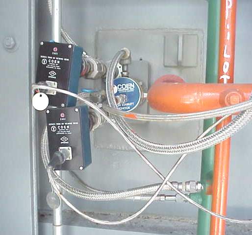
The burner has been supplied with all flame safety equipment and controls for safe operation.
System Operation
The burner is typically located after the second HP superheater section of the HRSG (”’Figure 7”’). During normal operations, the HRSG will operate without supplemental firing. Supplemental firing is required during periods of high steam demand or when power augmentation of the combustion turbine is required.
The burner is designed to supplement the energy available from the CT and uses the unused oxygen from CT exhaust gas.
- The duct burner should be brought online only after CT has attained 100% of its unfired base load condition.
- The burner should not be started in any other low load condition of CT. The duct burner will not work when CT is not in service, since no oxygen will be available to burn the fuel.
The entire operation sequence of the burner system is directed by BMS (burner management system). The burner should be started at its minimum turndown position and fuel flow gradually is increased per demand. The duct burner typically has a 10:1 turndown ratio. It is important to never exceed design heat release rate of the burner and the CT exhaust temperature downstream of it.
Several safety features are incorporated for safe operation of HRSG and duct burner. The fuel flow is controlled by the plant control system (DCS). The burner management system (BMS) provides the control of safety system that includes startup, shutdown, and trips of the duct burner. The burner management system (BMS) will typically be set to initiate a “trip” of the HRSG/burner on the occurrence of the following conditions:
Some HRSG trips:
- Steam temperature (SH) – very high
- Drum level (HP/IP/LP) – very, very low
- Firing temperature – very high
- Final steam pressure – very high
- HRSG “trip” sends a signal to trip CT and duct burner
Some Duct Burner trips:
- CT gas temperature at burner downstream high
- Scanner cooling airflow – very low
- Drum level (HP/LP) – very low
- Natural gas (fuel) pressure – very high
- Natural gas (fuel) pressure – very low
- CT not running at base load
- Flame failure (as sensed by burner flame scanners)
- Duct burner starting failure
Selective Catalytic Reduction System
This section describes the selective catalytic reduction (SCR) system, its components, and operation.
System Description
HRSG(s) are typically equipped with an SCR system. The system is designed to reduce the NOxemissions to as low as needed with a typical ammonia slip limit of 5 ppm at 15% O2at the HRSG exhaust stack exit.
”Ammonia slip is the amount of ammonia being released out the stack. ”
SCR System Components
The SCR system consists of the following:
- Catalyst housing and internal supports
- Ammonia injection grid and housing
- Ammonia flow control skid
- Ammonia distribution header including
- Manometers/instrumentation
- Catalyst loading doors
- Catalyst block hoist and monorail
The SCR system removes NOx(NO and NO2) through a selective catalytic reduction process. Aqueous ammonia (NH3) is used as the reducing agent. The process is selective because NH3reacts primarily with NO and NO2, as shown in the following equations:
4NO+4NH3+O2 =4N2+6H2O
NO+NO2+2NH3=2N2+3H2O
SCR Catalyst
The catalyst bed is typically made up of compact, homogeneous, honeycomb monolith ceramic elements. Substrates used in each element are a mixture of titanium dioxide (TiO2), tungsten oxide (WO3), and vanadium pentoxide.
Temperature
The typical catalyst is most effective in the temperature range between 635F and 75F. A degradation of NOxremoval efficiency and/or catalyst damage can occur if NH3is injected below 400F.