Boiling Heat Transfer
”The formation of steam bubbles along a heat transfer surface has a significant effect on the overall heat transfer rate.”
Boiling
In an industrial facility, convective heat transfer is used to remove heat from a heat transfer surface. The liquid used for cooling is usually in a compressed state, (that is, a subcooled fluid) at pressures higher than the normal saturation pressure for the given temperature. Under certain conditions, some type of boiling (usually nucleate boiling) can take place.
More than one type of boiling can take place within an industrial facility. A discussion of the boiling processes, specifically local and bulk boiling, will help the student understand these processes and provide a clearer picture of why bulk boiling (specifically film boiling) is to be avoided.
Nucleate Boiling
The most common type of local boiling encountered in industrial facilities is nucleate boiling. In nucleate boiling, steam bubbles form at the heat transfer surface and then break away and are carried into the main stream of the fluid. Such movement enhances heat transfer because the heat generated at the surface is carried directly into the fluid stream. Once in the main fluid stream, the bubbles collapse because the bulk temperature of the fluid is not as high as the heat transfer surface temperature where the bubbles were created. This heat transfer process is sometimes desirable because the energy created at the heat transfer surface is quickly and efficiently “carried” away.
Bulk Boiling
As system temperature increases or system pressure drops, the bulk fluid can reach saturation conditions. At this point, the bubbles entering the coolant channel will not collapse. The bubbles will tend to join together and form bigger steam bubbles. This phenomenon is referred to as bulk boiling. Bulk boiling can provide adequate heat transfer provided that the steam bubbles are carried away from the heat transfer surface and the surface is continually wetted with liquid water. When this cannot occur film boiling results.
Film Boiling
When the pressure of a system drops or the flow decreases, the bubbles cannot escape as quickly from the heat transfer surface. Likewise, if the temperature of the heat transfer surface is increased, more bubbles are created. As the temperature continues to increase, more bubbles are formed than can be efficiently carried away. The bubbles grow and group together, covering small areas of the heat transfer surface with a film of steam. This is known as ”partial film boiling”. Since steam has a lower convective heat transfer coefficient than water, the steam patches on the heat transfer surface act to insulate the surface making heat transfer more difficult. As the area of the heat transfer surface covered with steam increases, the temperature of the surface increases dramatically, while the heat flux from the surface decreases. This unstable situation continues until the affected surface is covered by a stable blanket of steam, preventing contact between the heat transfer surface and the liquid in the center of the flow channel. The condition after the stable steam blanket has formed is referred to as ”film boiling”.
The process of going from nucleate boiling to film boiling is graphically represented in Figure 1. The figure illustrates the effect of boiling on the relationship between the heat flux and the temperature difference between the heat transfer surface and the fluid passing it.
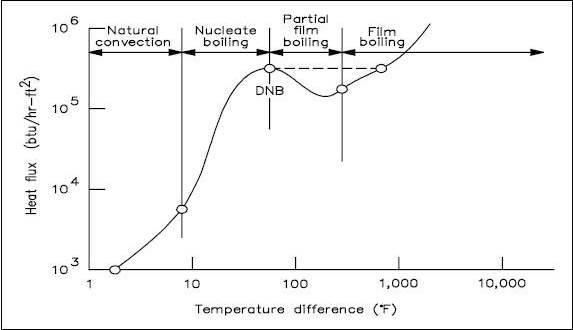
Four regions are represented in Figure 1. The first and second regions show that as heat flux increases, the temperature difference (surface to fluid) does not change very much. Better heat transfer occurs during nucleate boiling than during natural convection. As the heat flux increases, the bubbles become numerous enough that partial film boiling (part of the surface being blanketed with bubbles) occurs. This region is characterized by an increase in temperature difference and a decrease in heat flux. The increase in temperature difference thus causes total film boiling, in which steam completely blankets the heat transfer surface.
Departure from Nucleate Boiling and Critical Heat Flux
In practice, if the heat flux is increased, the transition from nucleate boiling to film boiling occurs suddenly, and the temperature difference increases rapidly, as shown by the dashed line in the figure. The point of transition from nucleate boiling to film boiling is called the point of departure from nucleate boiling, commonly written as DNB. The heat flux associated with DNB is commonly called the critical heat flux (CHF). In many applications, CHF is an important parameter. For example, in a boiler, if the critical heat flux is exceeded and DNB occurs at any location, the temperature difference required to transfer the heat being produced increases greatly.
The amount of heat transfer by convection can only be determined after the local heat transfer coefficient is determined. Such determination must be based on available experimental data. After experimental data has been correlated by dimensional analysis, it is a general practice to write an equation for the curve that has been drawn through the data and to compare experimental results with those obtained by analytical means. In the application of any empirical equation for forced convection to practical problems, it is important for the student to bear in mind that the predicted values of heat transfer coefficient are not exact. The values of heat transfer coefficients used by students may differ considerably from one student to another, depending on what source “book” the student has used to obtain the information. In turbulent and laminar flow, the accuracy of a heat transfer coefficient predicted from any available equation or graph may be no better than 30%.
Conduction Heat Transfer
Conduction heat transfer is the transfer of thermal energy by interactions between adjacent atoms and molecules of a solid. Conduction Conduction involves the transfer of heat by the interaction between adjacent molecules of a material. Heat transfer by conduction is dependent upon the driving “force” of temperature difference and the resistance to heat transfer. The resistance to heat transfer is dependent upon the nature and dimensions of the heat transfer medium. All heat transfer problems involve the temperature difference, the geometry, and the physical properties of the object being studied.
In conduction heat transfer problems, the object being studied is usually a solid. Convection problems involve a fluid medium. Radiation heat transfer problems involve either solid or fluid surfaces, separated by a gas, vapor, or vacuum. There are several ways to correlate the geometry, physical properties, and temperature difference of an object with the rate of heat transfer through the object. In conduction heat transfer, the most common means of correlation is through Fouriers Law of Conduction. The law, in its equation form, is used most often in its rectangular or cylindrical form (pipes and cylinders), both of which are presented below.
![]()
![]()
The use of Equations 2-4 and 2-5 in determining the amount of heat transferred by conduction is demonstrated in the following examples.
Conduction-Rectangular Coordinates
Example:
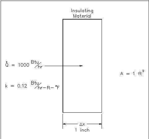
- 1000 Btu/hr is conducted through a section of insulating material shown in Figure 2 that measures 1 ft2 in cross-sectional area. The thickness is 1 in. and the thermal conductivity is 0.12 Btu/hr-ft-° F. Compute the temperature difference across the material.
![]()
Example:
- A concrete floor with a conductivity of 0.8 Btu/hr-ft-° F measures 30 ft by 40 ft with a thickness of 4 inches. The floor has a surface temperature of 70° F and the temperature beneath it is 60° F. What is the heat flux and the heat transfer rate through the floor?
Solution:
Using Equations 2-1 and 2-4:
![]()
Using Equation 2-3:
![]()
Equivalent Resistance Method
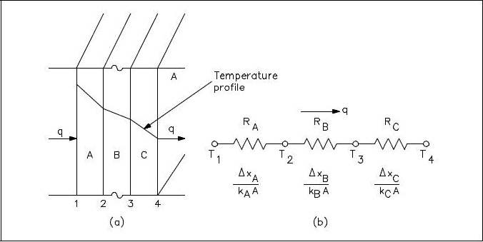
It is possible to compare heat transfer to current flow in electrical circuits. The heat transfer rate may be considered as a current flow and the combination of thermal conductivity, thickness of material, and area as a resistance to this flow. The temperature difference is the potential or driving function for the heat flow, resulting in the Fourier equation being written in a form similar to Ohms Law of Electrical Circuit Theory. If the thermal resistance term Δx/k is written as a resistance term where the resistance is the reciprocal of the thermal conductivity divided by the thickness of the material, the result is the conduction equation being analogous to electrical systems or networks. The electrical analogy may be used to solve complex problems involving both series and parallel thermal resistances. The student is referred to Figure 3, showing the equivalent resistance circuit. A typical conduction problem in its analogous electrical form is given in the following example, where the “electrical” Fourier equation may be written as follows.
![]()
Electrical Analogy
Example:
A composite protective wall is formed of a 1 in. copper plate, a 1/8 in. layer of asbestos, and a 2 in. layer of fiberglass. The thermal conductivities of the materials in units of Btu/hr-ft-oF are as follows: kCu = 240, kasb = 0.048, and kfib = 0.022. The overall temperature difference across the wall is 500XF. Calculate the thermal resistance of each layer of the wall and the heat transfer rate per unit area (heat flux) through the composite structure.
![]()
![]()
Conduction-Cylindrical Coordinates
Heat transfer across a rectangular solid is the most direct application of Fouriers law. Heat transfer across a pipe or heat exchanger tube wall is more complicated to evaluate. Across a cylindrical wall, the heat transfer surface area is continually increasing or decreasing. Figure 4 is a cross-sectional view of a pipe constructed of a homogeneous material.
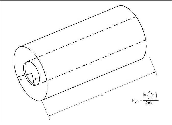
The surface area (A) for transferring heat through the pipe (neglecting the pipe ends) is directly proportional to the radius (r) of the pipe and the length (L) of the pipe.
A = 2πrL
As the radius increases from the inner wall to the outer wall, the heat transfer area increases.
The development of an equation evaluating heat transfer through an object with cylindrical geometry begins with Fouriers law Equation 2-5.
![]()
From the discussion above, it is seen that no simple expression for area is accurate. Neither the area of the inner surface nor the area of the outer surface alone can be used in the equation. For a problem involving cylindrical geometry, it is necessary to define a log mean cross-sectional area (Alm).
![]()
Substituting the expression 2πrL for area in Equation 2-7 allows the log mean area to be calculated from the inner and outer radius without first calculating the inner and outer area.
![]()
This expression for log mean area can be inserted into Equation 2-5, allowing us to calculate the heat transfer rate for cylindrical geometries.
![]()
Example:
A stainless steel pipe with a length of 35 ft has an inner diameter of 0.92 ft and an outer diameter of 1.08 ft. The temperature of the inner surface of the pipe is 122° F and the temperature of the outer surface is 118° F. The thermal conductivity of the stainless steel is 108 Btu/hr-ft-° F.
Calculate the heat transfer rate through the pipe.
Calculate the heat flux at the outer surface of the pipe.
![]()
![]()
Example:
A 10 ft length of pipe with an inner radius of 1 in and an outer radius of 1.25 in has an outer surface temperature of 250° F. The heat transfer rate is 30,000 Btu/hr. Find the interior surface temperature. Assume k = 25 Btu/hr-ft-° F.
![]()
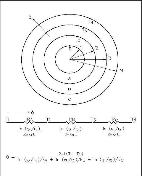
The evaluation of heat transfer through a cylindrical wall can be extended to include a composite body composed of several concentric, cylindrical layers, as shown in Figure 5.
Example:
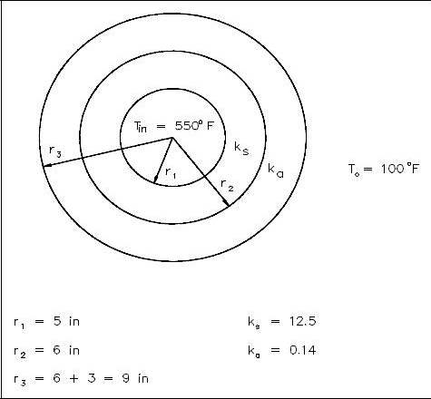
A thick-walled coolant pipe (ks = 12.5 Btu/hr-ft-° F) with 10 in. inside diameter (ID) and 12 in. outside diameter (OD) is covered with a 3 in. layer of asbestos insulation (ka = 0.14 Btu/hr-ft-° F) as shown in Figure 6. If the inside wall temperature of the pipe is maintained at 550° F, calculate the heat loss per foot of length. The outside temperature is 100° F.
![]()
Convection Heat Transfer
”Heat transfer by the motion and mixing of the molecules of a liquid or gas is called convection.”
Convection
Convection involves the transfer of heat by the motion and mixing of “macroscopic” portions of a fluid (that is, the flow of a fluid past a solid boundary). The term natural convection is used if this motion and mixing is caused by density variations resulting from temperature differences within the fluid. The term forced convection is used if this motion and mixing is caused by an outside force, such as a pump. The transfer of heat from a hot water radiator to a room is an example of heat transfer by natural convection. The transfer of heat from the surface of a heat exchanger to the bulk of a fluid being pumped through the heat exchanger is an example of forced convection.
Heat transfer by convection is more difficult to analyze than heat transfer by conduction because no single property of the heat transfer medium, such as thermal conductivity, can be defined to describe the mechanism. Heat transfer by convection varies from situation to situation (upon the fluid flow conditions), and it is frequently coupled with the mode of fluid flow. In practice, analysis of heat transfer by convection is treated empirically (by direct observation).
Convection heat transfer is treated empirically because of the factors that affect the stagnant film thickness:
- Fluid velocity
- Fluid viscosity
- Heat flux
- Surface roughness
- Type of flow (single-phase/two-phase)
Convection involves the transfer of heat between a surface at a given temperature (Ts) and fluid at a bulk temperature (Tb). The exact definition of the bulk temperature (Tb) varies depending on the details of the situation. For flow adjacent to a hot or cold surface, Tb is the temperature of the fluid “far” from the surface. For boiling or condensation, Tb is the saturation temperature of the fluid. For flow in a pipe, Tb is the average temperature measured at a particular cross-section of the pipe.
The basic relationship for heat transfer by convection has the same form as that for heat transfer by conduction:
![]()
The convective heat transfer coefficient (h) is dependent upon the physical properties of the fluid and the physical situation. Typically, the convective heat transfer coefficient for laminar flow is relatively low compared to the convective heat transfer coefficient for turbulent flow. This is due to turbulent flow having a thinner stagnant fluid film layer on the heat transfer surface. Values of h have been measured and tabulated for the commonly encountered fluids and flow situations occurring during heat transfer by convection.
Example:
A 22 foot uninsulated steam line crosses a room. The outer diameter of the steam line is 18 in. and the outer surface temperature is 280° F. The convective heat transfer coefficient for the air is 18 Btu/hr-ft2-° F. Calculate the heat transfer rate from the pipe into the room if the room temperature is 72° F.
![]()
Many applications involving convective heat transfer take place within pipes, tubes, or some similar cylindrical device. In such circumstances, the surface area of heat transfer normally given in the convection equation
![]()
varies as heat passes through the cylinder. In addition, the temperature difference existing between the inside and the outside of the pipe, as well as the temperature differences along the pipe, necessitates the use of some average temperature value in order to analyze the problem. This average temperature difference is called the log mean temperature difference (LMTD), described earlier.
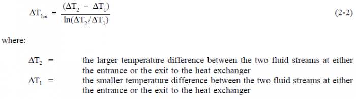
It is the temperature difference at one end of the heat exchanger minus the temperature difference at the other end of the heat exchanger, divided by the natural logarithm of the ratio of these two temperature differences. The above definition for LMTD involves two important assumptions:
(1) the fluid specific heats do not vary significantly with temperature, and (2) the convection heat transfer coefficients are relatively constant throughout the heat exchanger.
Overall Heat Transfer Coefficient
Many of the heat transfer processes encountered in nuclear facilities involve a combination of both conduction and convection. For example, heat transfer in a steam generator involves convection from the bulk of the reactor coolant to the steam generator inner tube surface, conduction through the tube wall, and convection from the outer tube surface to the secondary side fluid.
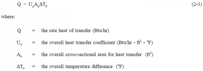
In cases of combined heat transfer for a heat exchanger, there are two values for h. There is the convective heat transfer coefficient (h) for the fluid film inside the tubes and a convective heat transfer coefficient for the fluid film outside the tubes. The thermal conductivity (k) and thickness (Δx) of the tube wall must also be accounted for. An additional term (Uo), called the overall heat transfer coefficient, must be used instead. It is common practice to relate the total rate of heat transfer to the cross-sectional area for heat transfer (Ao) and the overall heat transfer coefficient (Uo). The relationship of the overall heat transfer coefficient to the individual conduction and convection terms is shown in Figure 7.
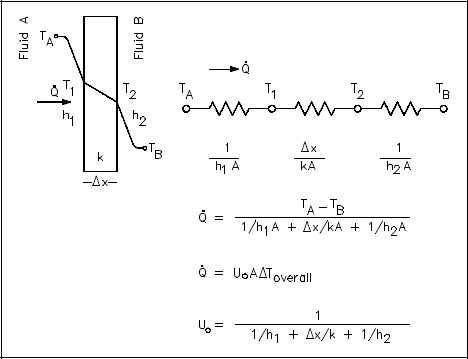
Recalling Equation 2-3:
![]()
where Uo is defined in Figure 8.
An example of this concept applied to cylindrical geometry is illustrated by Figure 8, which shows a typical combined heat transfer situation.
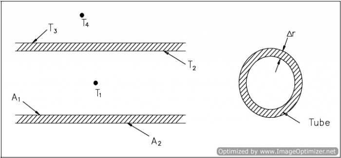
Using the figure representing flow in a pipe, heat transfer by convection occurs between temperatures T1 and T2; heat transfer by conduction occurs between temperatures T2 and T3; and heat transfer occurs by convection between temperatures T3 and T4. Thus, there are three processes involved. Each has an associated heat transfer coefficient, cross-sectional area for heat transfer, and temperature difference. The basic relationships for these three processes can be expressed using Equations 2-5 and 2-9.
![]()
![]()
ΔTo can be expressed as the sum of the ΔT of the three individual processes.
![]()
If the basic relationship for each process is solved for its associated temperature difference and substituted into the expression for ΔTo above, the following relationship results.
![]()
This relationship can be modified by selecting a reference cross-sectional area Ao.
![]()
![]()
Equation 2-10 for the overall heat transfer coefficient in cylindrical geometry is relatively difficult to work with. The equation can be simplified without losing much accuracy if the tube that is being analyzed is thin-walled, that is the tube wall thickness is small compared to the tube diameter. For a thin-walled tube, the inner surface area (A1), outer surface area (A2), and log mean surface area (A1m), are all very close to being equal. Assuming that A1, A2, and A1m are equal to each other and also equal to Ao allows us to cancel out all the area terms in the denominator of Equation 2-11.
This results in a much simpler expression that is similar to the one developed for a flat plate heat exchanger in Figure 7.
![]()
The convection heat transfer process is strongly dependent upon the properties of the fluid being considered. Correspondingly, the convective heat transfer coefficient (h), the overall coefficient (Uo), and the other fluid properties may vary substantially for the fluid if it experiences a large temperature change during its path through the convective heat transfer device. This is especially true if the fluids properties are strongly temperature dependent. Under such circumstances, the temperature at which the properties are “looked-up” must be some type of average value, rather than using either the inlet or outlet temperature value.
For internal flow, the bulk or average value of temperature is obtained analytically through the use of conservation of energy. For external flow, an average film temperature is normally calculated, which is an average of the free stream temperature and the solid surface temperature. In any case, an average value of temperature is used to obtain the fluid properties to be used in the heat transfer problem. The following example shows the use of such principles by solving a convective heat transfer problem in which the bulk temperature is calculated.
Example:
- A flat wall is exposed to the environment. The wall is covered with a layer of insulation 1 in. thick whose thermal conductivity is 0.8 Btu/hr-ft-° F. The temperature of the wall on the inside of the insulation is 600° F. The wall loses heat to the environment by convection on the surface of the insulation. The average value of the convection heat transfer coefficient on the insulation surface is 950 Btu/hr-ft2-° F. Compute the bulk temperature of the environment (Tb) if the outer surface of the insulation does not exceed 105° F.
Solution:
![]()
![]()
Heat Exchangers
”Heat exchangers are devices that are used to transfer thermal energy from one fluid to another without mixing the two fluids.”
The transfer of thermal energy between fluids is one of the most important and frequently used processes in engineering. The transfer of heat is usually accomplished by means of a device known as a heat exchanger. Common applications of heat exchangers in an industrial facility include boilers, fan coolers, cooling water heat exchangers, and condensers.
The basic design of a heat exchanger normally has two fluids of different temperatures separated by some conducting medium. The most common design has one fluid flowing through metal tubes and the other fluid flowing around the tubes. On either side of the tube, heat is transferred by convection. Heat is transferred through the tube wall by conduction.
Heat exchangers may be divided into several categories or classifications. In the most commonly used type of heat exchanger, two fluids of different temperature flow in spaces separated by a tube wall. They transfer heat by convection and by conduction through the wall. This type is referred to as an “ordinary heat exchanger,” as compared to the other two types classified as “regenerators” and “cooling towers.”
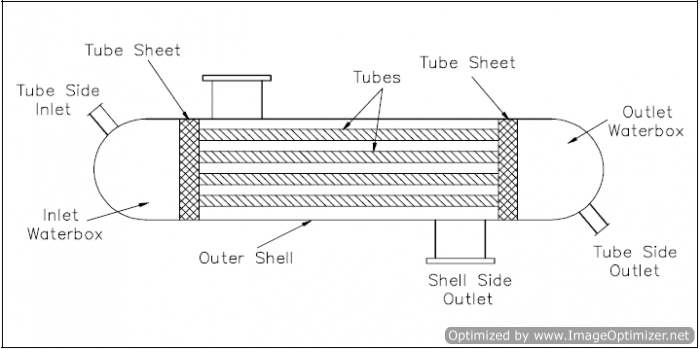
An ordinary heat exchanger is single-phase or two-phase. In a single-phase heat exchanger, both of the fluids (cooled and heated) remain in their initial gaseous or liquid states. In two-phase exchangers, either of the fluids may change its phase during the heat exchange process. The steam generator and main condenser are of the two-phase, ordinary heat exchanger classification. Single-phase heat exchangers are usually of the tube-and-shell type; that is, the exchanger consists of a set of tubes in a container called a shell (Figure 9). At the ends of the heat exchanger, the tube-side fluid is separated from the shell-side fluid by a tube sheet. The design of two-phase exchangers is essentially the same as that of single-phase exchangers.
Parallel and Counter-Flow Designs
Although ordinary heat exchangers may be extremely different in design and construction and may be of the single- or two-phase type, their modes of operation and effectiveness are largely determined by the direction of the fluid flow within the exchanger.
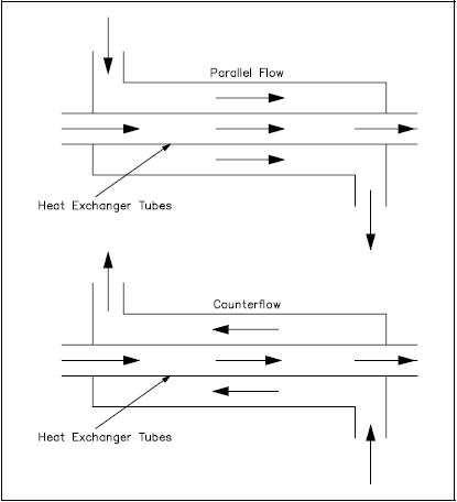
The most common arrangements for flow paths within a heat exchanger are counter-flow and parallel flow. A counter-flow heat exchanger is one in which the direction of the flow of one of the working fluids is opposite to the direction to the flow of the other fluid. In a parallel flow exchanger, both fluids in the heat exchanger flow in the same direction.
Figure 10 represents the directions of fluid flow in the parallel and counter-flow exchangers. Under comparable conditions, more heat is transferred in a counter-flow arrangement than in a parallel flow heat exchanger.
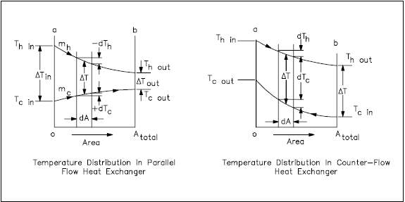
The temperature profiles of the two heat exchangers indicate two major disadvantages in the parallel-flow design. First, the large temperature difference at the ends (Figure 11) causes large thermal stresses. The opposing expansion and contraction of the construction materials due to diverse fluid temperatures can lead to eventual material failure. Second, the temperature of the cold fluid exiting the heat exchanger never exceeds the lowest temperature of the hot fluid. This relationship is a distinct disadvantage if the design purpose is to raise the temperature of the cold fluid.
The design of a parallel flow heat exchanger is advantageous when two fluids are required to be brought to nearly the same temperature.
The counter-flow heat exchanger has three significant advantages over the parallel flow design. First, the more uniform temperature difference between the two fluids minimizes the thermal stresses throughout the exchanger. Second, the outlet temperature of the cold fluid can approach the highest temperature of the hot fluid (the inlet temperature). Third, the more uniform temperature difference produces a more uniform rate of heat transfer throughout the heat exchanger.
Whether parallel or counter-flow, heat transfer within the heat exchanger involves both conduction and convection. One fluid (hot) convectively transfers heat to the tube wall where conduction takes place across the tube to the opposite wall. The heat is then convectively transferred to the second fluid. Because this process takes place over the entire length of the exchanger, the temperature of the fluids as they flow through the exchanger is not generally constant, but varies over the entire length, as indicated in Figure 11. The rate of heat transfer varies along the length of the exchanger tubes because its value depends upon the temperature difference between the hot and the cold fluid at the point being viewed.
Non-Regenerative Heat Exchanger
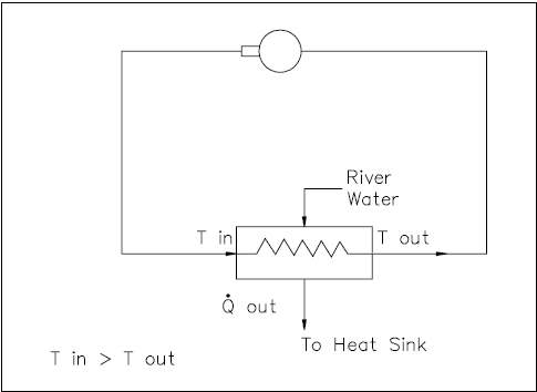
Applications of heat exchangers may be classified as either regenerative or non-regenerative. The non-regenerative application is the most frequent and involves two separate fluids. One fluid cools or heats the other with no interconnection between the two fluids. Heat that is removed from the hotter fluid is usually rejected to the environment or some other heat sink (Figure 12).
Regenerative Heat Exchanger
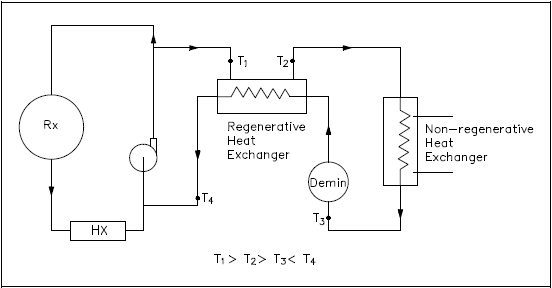
A regenerative heat exchanger typically uses the fluid from a different area of the same system for both the hot and cold fluids. The primary coolant to be purified is drawn out of the primary system, passed through a regenerative heat exchanger, non-regenerative heat exchanger, demineralizer, back through the regenerative heat exchanger, and returned to the primary system (Figure 13).
In the regenerative heat exchanger, the water returning to the primary system is pre-heated by the water entering the purification system. This accomplishes two objectives. The first is to minimize the thermal stress in the primary system piping due to the cold temperature of the purified coolant being returned to the primary system.
The second is to reduce the temperature of the water entering the purification system prior to reaching the non-regenerative heat exchanger, allowing use of a smaller heat exchanger to achieve the desired temperature for purification. The primary advantage of a regenerative heat exchanger application is conservation of system energy (that is, less loss of system energy due to the cooling of the fluid).
Cooling Towers
The typical function of a cooling tower is to cool the water of a steam power plant by air that is brought into direct contact with the water. The water is mixed with vapor that diffuses from the condensate into the air. The formation of the vapor requires a considerable removal of internal energy from the water; the internal energy becomes “latent heat” of the vapor. Heat and mass exchange are coupled in this process, which is a steady-state process like the heat exchange in the ordinary heat exchanger.
Wooden cooling towers are sometimes employed in factories of various industries. They generally consists of large chambers loosely filled with trays or similar wooden elements of construction. The water to be cooled is pumped to the top of the tower where it is distributed by spray or wooden troughs. It then falls through the tower, splashing down from deck to deck. A part of it evaporates into the air that passes through the tower. The enthalpy needed for the evaporation is taken from the water and transferred to the air, which is heated while the water cools. The air flow is either horizontal due to wind currents (cross flow) or vertically upward in counter-flow to the falling water. The counter-flow is caused by the chimney effect of the warm humid air in the tower or by fans at the bottom (forced draft) or at the top (induced flow) of the tower. Mechanical draft towers are more economical to construct and smaller in size than natural-convection towers of the same cooling capacity.
Log Mean Temperature Difference Application To Heat Exchangers
In order to solve certain heat exchanger problems, a log mean temperature difference (LMTD or Tlm) must be evaluated before the heat removal from the heat exchanger is determined. The following example demonstrates such a calculation.
Example:
- A liquid-to-liquid counterflow heat exchanger is used as part of an auxiliary system at an industrial facility. The heat exchanger is used to heat a cold fluid from 120° F to 310° F.
- Assuming that the hot fluid enters at 500° F and leaves at 400° F, calculate the LMTD for the exchanger.
Solution:
![]()
The solution to the heat exchanger problem may be simple enough to be represented by a straight-forward overall balance or may be so detailed as to require integral calculus. A steam generator, for example, can be analyzed by an overall energy balance from the feedwater inlet to the steam outlet in which the amount of heat transferred can be expressed simply as Q=ṁ Δh, where ṁ is the mass flow rate of the secondary coolant and Δh is the change in enthalpy of the fluid. The same steam generator can also be analyzed by an energy balance on the primary flow stream with the equation Q=ṁ cp ΔT where ṁ, cp, and ΔT are the mass flow rate, specific heat capacity, and temperature change of the primary coolant. The heat transfer rate of the steam generator can also be determined by comparing the temperatures on the primary and secondary sides with the heat transfer characteristics of the steam generator using the equation Q=Uo Ao ΔTlm.
Condensers are also examples of components found in industrial facilities where the concept of LMTD is needed to address certain problems. When the steam enters the condenser, it gives up its latent heat of vaporization to the circulating water and changes phase to a liquid. Because condensation is taking place, it is appropriate to term this the latent heat of condensation. After the steam condenses, the saturated liquid will continue to transfer some heat to the circulating water system as it continues to fall to the bottom (hotwell) of the condenser. This continued cooling is called subcooling and is necessary to prevent cavitation in the condensate pumps.
The solution to condenser problems is approached in the same manner as those for steam generators, as shown in the following example.
Overall Heat Transfer Coefficient
When dealing with heat transfer across heat exchanger tubes, an overall heat transfer coefficient, Uo, must be calculated. Earlier in this module we looked at a method for calculating Uo for both rectangular and cylindrical coordinates. Since the thickness of a condenser tube wall is so small and the cross-sectional area for heat transfer is relatively constant, we can use Equation 2-11 to calculate Uo.
![]()
Example:
Referring to the convection section of this manual, calculate the heat rate per foot of tube from a condenser under the following conditions. T = 232EF. The outer lm diameter of the copper condenser tube is 0.75 in. with a wall thickness of 0.1 in. Assume the inner convective heat transfer coefficient is 2000 Btu/hr-ft2-EF, and the thermal conductivity of copper is 200 Btu/hr-ft-EF. The outer convective heat transfer coefficient is 1500 Btu/hr-ft2-EF.
![]()
Heat Transfer Terminology
”To understand and communicate in the thermal science field, certain terms and expressions must be learned in heat transfer.”
Heat and Temperature
In describing heat transfer problems, students often make the mistake of interchangeably using the terms heat and temperature. Actually, there is a distinct difference between the two. ”Temperature” is a measure of the amount of energy possessed by the molecules of a substance. It is a relative measure of how hot or cold a substance is and can be used to predict the direction of heat transfer. The symbol for temperature is T. The common scales for measuring temperature are the Fahrenheit, Rankine, Celsius, and Kelvin temperature scales.
”Heat” is energy in transit. The transfer of energy as heat occurs at the molecular level as a result of a temperature difference. Heat is capable of being transmitted through solids and fluids by conduction, through fluids by convection, and through empty space by radiation. The symbol for heat is Q. Common units for measuring heat are the British Thermal Unit (Btu) in the English system of units and the calorie in the SI system (International System of Units).
Heat and Work
Distinction should also be made between the energy terms ”heat” and ”work”. Both represent energy in transition. Work is the transfer of energy resulting from a force acting through a distance. Heat is energy transferred as the result of a temperature difference. Neither heat nor work are thermodynamic properties of a system. Heat can be transferred into or out of a system and work can be done on or by a system, but a system cannot contain or store either heat or work. Heat into a system and work out of a system are considered positive quantities.
When a temperature difference exists across a boundary, the Second Law of Thermodynamics indicates the natural flow of energy is from the hotter body to the colder body. The Second Law of Thermodynamics denies the possibility of ever completely converting into work all the heat supplied to a system operating in a cycle. The Second Law of Thermodynamics, described by Max Planck in 1903, states that:
- It is impossible to construct an engine that will work in a complete cycle and
produce no other effect except the raising of a weight and the cooling of a
reservoir.
The second law says that if you draw heat from a reservoir to raise a weight, lowering the weight will not generate enough heat to return the reservoir to its original temperature, and eventually the cycle will stop. If two blocks of metal at different temperatures are thermally insulated from their surroundings and are brought into contact with each other the heat will flow from the hotter to the colder. Eventually the two blocks will reach the same temperature, and heat transfer will cease. Energy has not been lost, but instead some energy has been transferred from one block to another.
Modes of Transferring Heat
Heat is always transferred when a temperature difference exists between two bodies. There are three basic modes of heat transfer:
- ”Conduction” involves the transfer of heat by the interactions of atoms or molecules of a material through which the heat is being transferred.
- ”Convection” involves the transfer of heat by the mixing and motion of macroscopic portions of a fluid.
- ”Radiation”, or radiant heat transfer, involves the transfer of heat by electromagnetic radiation that arises due to the temperature of a body.
The three modes of heat transfer will be discussed in greater detail in the subsequent chapters of this module.
Heat Flux
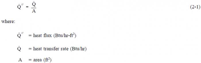
The rate at which heat is transferred is represented by the symbol  Common units for heat transfer rate is Btu/hr. Sometimes it is important to determine the heat transfer rate per unit area, or ”heat flux”, which has the symbol
  Units for heat flux are Btu/hr-ft2. The heat flux can be determined by dividing the heat transfer rate by the area through which the heat is being transferred.
Thermal Conductivity
The heat transfer characteristics of a solid material are measured by a property called the ”thermal conductivity” (k) measured in Btu/hr-ft- ° F. It is a measure of a substances ability to transfer heat through a solid by conduction. The thermal conductivity of most liquids and solids varies with temperature. For vapors, it depends upon pressure.
Log Mean Temperature Difference
In heat exchanger applications, the inlet and outlet temperatures are commonly specified based on the fluid in the tubes. The temperature change that takes place across the heat exchanger from the entrance to the exit is not linear. A precise temperature change between two fluids across the heat exchanger is best represented by the ”log mean temperature difference” (LMTD or ΔTlm), defined in Equation 2-2.
Convective Heat Transfer Coefficient
The ”convective heat transfer coefficient” (h), defines, in part, the heat transfer due to convection. The convective heat transfer coefficient is sometimes referred to as a film coefficient and represents the thermal resistance of a relatively stagnant layer of fluid between a heat transfer surface and the fluid medium. Common units used to measure the convective heat transfer coefficient are Btu/hr – ft2 – ° F.
Overall Heat Transfer Coefficient
In the case of combined heat transfer, it is common practice to relate the total rate of heat Transfer [[Image:(q).png|framed]] the overall cross-sectional area for heat transfer (Ao), and the overall temperature difference [[Image:T.png|framed]] using the ”overall heat transfer coefficient” (Uo). The overall heat transfer coefficient combines the heat transfer coefficient of the two heat exchanger fluids and the thermal conductivity of the heat exchanger tubes. Uo is specific to the heat exchanger and the fluids that are used in the heat exchanger.
Bulk Temperature
The fluid temperature (Tb), referred to as the ”bulk temperature”, varies according to the details of the situation. For flow adjacent to a hot or cold surface, Tb is the temperature of the fluid that is “far” from the surface, for instance, the center of the flow channel. For boiling or condensation, Tb is equal to the saturation temperature.
Radiant Heat Transfer
”Radiant heat transfer is thermal energy transferred by means of electromagnetic waves or particles.”
Thermal Radiation
Radiant heat transfer involves the transfer of heat by electromagnetic radiation that arises due to the temperature of a body. Most energy of this type is in the infra-red region of the electromagnetic spectrum although some of it is in the visible region. The term thermal radiation is frequently used to distinguish this form of electromagnetic radiation from other forms, such as radio waves, x-rays, or gamma rays. The transfer of heat from a fireplace across a room in the line of sight is an example of radiant heat transfer.
Radiant heat transfer does not need a medium, such as air or metal, to take place. Any material that has a temperature above absolute zero gives off some radiant energy. When a cloud covers the sun, both its heat and light diminish. This is one of the most familiar examples of heat transfer by thermal radiation.
Black Body Radiation
A body that emits the maximum amount of heat for its absolute temperature is called a black body. Radiant heat transfer rate from a black body to its surroundings can be expressed by the following equation.
![]()
Two black bodies that radiate toward each other have a net heat flux between them. The net flow rate of heat between them is given by an adaptation of Equation 2-12.
![]()
All bodies above absolute zero temperature radiate some heat. The sun and earth both radiate heat toward each other. This seems to violate the Second Law of Thermodynamics, which states that heat cannot flow from a cold body to a hot body. The paradox is resolved by the fact that each body must be in direct line of sight of the other to receive radiation from it. Therefore, whenever the cool body is radiating heat to the hot body, the hot body must also be radiating heat to the cool body. Since the hot body radiates more heat (due to its higher temperature) than the cold body, the net flow of heat is from hot to cold, and the second law is still satisfied.
Emissivity
Real objects do not radiate as much heat as a perfect black body. They radiate less heat than a black body and are called gray bodies. To take into account the fact that real objects are gray bodies, Equation 2-12 is modified to be of the following form.
![]()
Emissivity is simply a factor by which we multiply the black body heat transfer to take into account that the black body is the ideal case. Emissivity is a dimensionless number and has a maximum value of 1.0.
Radiation Configuration Factor
Radiative heat transfer rate between two gray bodies can be calculated by the equation stated below.
![]()
where:
fa = is the shape factor, which depends on the spatial arrangement of the two objects(dimensionless)
fe = is the emissivity factor, which depends on the emissivities of both objects (dimensionless)
The two separate terms fa and fe can be combined and given the symbol f. The heat flow between two gray bodies can now be determined by the following equation:
![]()
The symbol (f) is a dimensionless factor sometimes called the ”radiation configuration factor”, which takes into account the emissivity of both bodies and their relative geometry. The radiation configuration factor is usually found in a text book for the given situation. Once the configuration factor is obtained, the overall net heat flux can be determined. Radiant heat flux should only be included in a problem when it is greater than 20% of the problem.
Example:
- Calculate the radiant heat between the floor (15 ft x 15 ft) of a furnace and the roof, if the two are located 10 ft apart. The floor and roof temperatures are 2000° F and 600° F, respectively. Assume that the floor and the roof have black surfaces.
Solution:
![]()
Tables from a reference book, or supplied by the instructor, give:
![]()